Relays Types, Applications and Importance

Exploring the Overcurrent Relays in Electrical Power Systems

Electrical power systems heavily rely on robust and efficient protection schemes to ensure the stability and safety of the grid. Electrical power systems comprise intricate circuits that are susceptible to faults, including ground faults, surge events, and overloads. Without proper protection, these faults can result in severe equipment damage, posing operational risks and shortening the system’s lifespan. These relays play a pivotal role in detecting abnormal conditions and promptly initiating corrective actions. Overcurrent protection is a critical element of modern power system operationsutilizing relays that rapidly detect fault currents and disconnect the affected areas, thereby ensuring the safety and stability of the network.

Overcurrent relays play a crucial role in overload automation monitoring within electrical power systems. These relays protect circuits by detecting abnormal fault currents, overloads, and ground faults, minimizing equipment damage and enhancing functionality. Their precise calibration ensures selectivity between protection devices, improving operations and preventing unnecessary failures or nuisance trips. They operate on principles of induction and magnetic field interaction, reacting to surges and thereby maintaining the system’s lifespan. Proper use of infrastructure reduces risk, safeguards machinery, and addresses the needs of varying loads and scenarios. Integrated with monitoring systems, overcurrent relays extend the capabilities of traditional fuses for improved power system protection.

What Are Overcurrent Relays

Overcurrent relays are intelligent devices that monitor electrical loads and detect any deviation beyond their designed range. Their primary function is to identify excessive current caused by overloads or ground faults and isolate the affected circuits. When the current exceeds pre-set thresholds, indicative of abnormal conditions or faults, overcurrent relays act swiftly to initiate corrective actions. By measuring and comparing current levels, these relays play a pivotal role in preventing damage to electrical equipment, minimizing downtime, and enhancing overall system reliability. Overcurrent relays play a crucial role in maintaining the integrity and safety of power systems, responding promptly to abnormal situations, and significantly contributing to the overall resilience of the electrical grid.

Characteristics of Overcurrent Relays

Overcurrent relays are defined by several core principles, including selectivity, response range, and thermal effects. Proper selectivity ensures that only the faulty section of the network is disconnected, maintaining stability in the remaining circuits. They are primarily made with semiconductor switches, such as thyristors. Digital relays have two states, ON and OFF, which can be represented by the binary digits 1 and 0, respectively.

 They must respond effectively across a broad range of loads, accounting for transient events like surges and heat generation caused by sustained fault conditions. Understanding these effects is crucial in designing systems that prevent nuisance tripping and ensure optimal system layer protection through the coordination of relays and fuses.  The overcurrent relays can be categorized into various types based on their characteristics, which are:

  • Instantaneous Overcurrent Relays
  • Definite Time Overcurrent Relays
  • Inverse-time Overcurrent Relays
  • Directional overcurrent relays

Instantaneous Overcurrent Relays
Instantaneous Overcurrent Relays

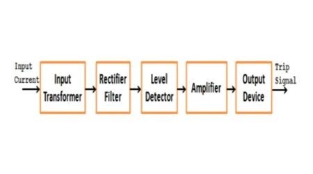
The block schematic diagram of the static instantaneous overcurrent relay is shown in the figure. The current derived from the CT is fed to the input transformer, which gives a proportional output voltage. The input transformer features an air gap in the iron core, which provides linearity in the current-voltage relationship up to the expected current value. It is supplied with a tapping on its secondary winding to obtain different contemporary settings. The transformer’s output voltage is rectified through a rectifier and then filtered in a single stage to avoid undesirable time delays in filtering and ensure high-speed operation. A zener diode incorporates a limit to ensure safe rectified voltage values during high input currents in fault conditions. The level detector compares a preset pickup value against a fixed portion of the rectified and filtered voltage, via a potential divider. If it surpasses the pick-up value, the output issues a trip signal through an amplifier. The output device may be a static thyristor circuit or an electromagnetic slave relay.

Definite Time Overcurrent Relays

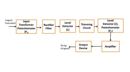
The operating time of overcurrent relays remains constant, regardless of the magnitude of the fault current. In this case, an intentional time delay is introduced through a timing circuit. The figure below shows a simplified block diagram of a definite-time overcurrent relay. These relays introduce a fixed time delay in their process, independent of fault magnitude. They are commonly used in cable and equipment protection where timing must be precisely calibrated to avoid premature failure.

The input current signal derived from the main CT is converted to a proportional voltage signal by the input transformer and then rectified, filtered, and compared with the preset threshold value of the level detector (1). If the voltage exceeds the preset threshold value, the level detector generates an output voltage; thereby, the capacitor C of the RC timing circuit begins to charge. When the voltage across the capacitor exceeds the preset threshold value (VT) of the level detector (2), a signal is generated through the amplifier, along with a time setting.
Definite Time Overcurrent Relays
If VT is the threshold value of the level detector, the time TC required to reach this voltage depends up, on the charging time of the capacitor C of the RC timing circuit, given by,
                                    TC = RCloge [V / (V-VT)]

If V, R, and C remain constant, the charging time for a specific VT value will stay consistent. The time TC can be varied by varying R-C combinations and VT. In this case, the capacitor is charged from a fixed DC voltage. The output, the voltage of the level detector (1), the relay’s operating time for particular R and C values of the timing circuit, and VT of the level detector (2) will be constant for different fault current values.

Inverse-Time Overcurrent Relay

The operating time of the inverse-time overcurrent relays decreases with increasing fault current. For this relay with an inverse-time characteristic, the capacitor in the timing circuit is charged from a voltage proportional to the current.
Inverse-Time Overcurrent Relay

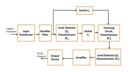
The figure shows the block diagram of the inverse-time overcurrent relay.

The input transformer converts the current signal into a proportional voltage, which is then rectified, filtered, and compared with a reference voltage (set by level detector 1, controlled by potentiometer P1). Under normal conditions, with a low input current, switch S1 is on, short-circuiting capacitor C in the RC timing circuit, and switch S2 is off. When the input voltage exceeds the preset reference voltage of level detector 1, S1 switches OFF, and S2 switches ON. The charging of capacitor C in the timing circuit begins at a voltage proportional to the current.

These relays dynamically adjust their trip timing, making them ideal for overloads and fault currents that increase over time. They are particularly effective in distribution systems where load capabilities and operations vary throughout the day.

Both switches, S1 and S2, consist of static components. When the voltage across capacitor C of the timing circuit exceeds the reference voltage of the level detector (2), set by potentiometer P3, a signal is sent to the output device through an amplifier. Finally, the output device issues the trip signal. Here, the transformer’s secondary tap and potentiometer P1 provide the plug setting multiplier, and potentiometers P2 and P3 determine the time multiplier setting.

Directional Overcurrent Relays

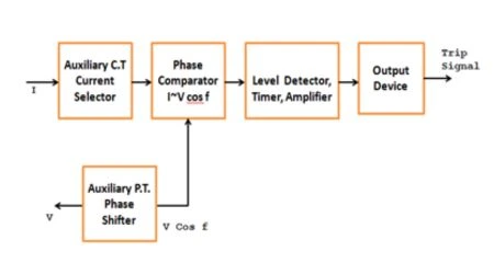
The directional overcurrent relays incorporate a directional unit that responds to power flow in a specified direction. The directional relay detects the movement of power flow by measuring the phase difference (Φ) between voltage (V) and current (I). When Φ exceeds a certain value, it operates. The directional relay is a double-acting quantity relay with two inputs: current I from the current transformer (CT) and voltage V from the potential transformer (PT).

They also analyze the source and direction of current flow to avoid false trips. These are ideal in scenarios involving parallel feeders or ring mains. Their mechanism relies on phase comparison logic, providing reliable performance even in challenging ground conditions with low voltages.
Under fault conditions, electromagnetic directional overcurrent relays experience affected discrimination when voltage drops to very low values. This problem is less serious in static directional relays because the static comparators used are inherently very sensitive. They can give a reliable performance up to 1% of the system voltage within the minimum fault voltage.

Directional Overcurrent Relays

The figure above shows a simplified block diagram of the directional overcurrent relay. The inputs V and I are applied to the phase comparator. A phase shifter is added to the voltage input circuit before applying it to the phase comparator to achieve the maximum output under fault conditions. The phase comparator’s result is fed to the level detector, and subsequently, it is transmitted to the output device via an amplifier. If the phase comparator’s output exceeds the level detector’s preset reference voltage, the output device issues the trip signal. Two main types of phase comparators are employed for this purpose. The Hall effect type, utilized in the USSR, is one of them. In contrast, all other countries have preferred the rectifier bridge type of comparator due to its lower cost and the higher output obtainable compared to the Hall elements.

Conclusion

In conclusion, overcurrent relays are essential to electrical power systems, enabling them to respond to abnormal conditions promptly. Their diverse characteristics cater to various grid requirements, offering faster response times, heightened accuracy, and reduced maintenance. The electronic nature of static relays ensures efficiency compared to traditional counterparts. These relays safeguard equipment and maintain grid stability, showcasing evolution and sophistication in power system protection. They play a pivotal role in ensuring the resilience and reliability of modern electrical networks.

FAQs

What is a static overcurrent relay, and how does it work?

The static overcurrent relay is an electronic protection device that identifies abnormal current levels in power systems. It operates by measuring current magnitudes and comparing them to preset thresholds. When the current exceeds the set values, the relay trips the circuit breaker, isolating the faulty section.

What are the advantages of using static overcurrent relays over traditional electromechanical relays?

Static overcurrent relays offer several advantages, including faster response times, higher accuracy, better sensitivity, and reduced maintenance requirements due to the absence of moving parts. They also provide more precise control over the tripping curves, allowing customization for specific applications.

What are the main applications of static overcurrent relays in power systems?

Static overcurrent relays are widely used in various power systems, including transmission lines, distribution systems, and generator protection systems. Common applications include load shedding, fault detection, and coordination with other protective devices.

Why are overcurrent relays crucial in power systems?

Overcurrent relays are crucial as they rapidly detect abnormal current levels, preventing damage to electrical equipment and ensuring grid stability. Their swift response minimizes downtime and mitigates potential hazards, contributing to the overall resilience of power systems.

Supporting Article

Types of Protective Relays

Difference Between Overcurrent and Undervoltage

Jessica

Jessica, at just 27 years old, is a passionate trailblazer in the world of physics and engineering. Her insatiable curiosity about the mysteries of the universe and a knack for simplifying complex concepts have made her a rising star in the field. As a Quantum Mechanics Enthusiast, Jessica delves into the deepest realms of theoretical physics with a unique and engaging perspective. Her love for unraveling the secrets of the quantum world is infectious, making even the most perplexing ideas accessible to enthusiasts and newcomers alike.

Leave a Reply

Your email address will not be published. Required fields are marked *