

Differences Between Series and Parallel Circuits
When exploring electrical circuits, understanding the differences between series and parallel configurations is crucial. Series circuits connect components end-to-end, creating a single path for current, while parallel circuits connect components across the same voltage points, allowing multiple paths. Each has unique behaviors affecting how they influence voltage, current, and resistance. These distinctions are crucial when considering efficiency and reliability in electrical systems. Curious about how these differences play out in real-world applications?
Key Takeaways
- Series circuits create a single current path, while parallel circuits allow multiple paths for current flow.
- In series circuits, the total resistance is the sum of the individual resistances; in parallel circuits, the total resistance is less than the resistance of the smallest resistor.
- Voltage divides among components in series circuits, but remains constant across each component in parallel circuits.
- A failure in a series circuit stops current flow, whereas in parallel circuits, other components continue working.
- Series circuits have the same current flowing through all components; parallel circuits have different currents based on the resistance of each branch.
Overview of Series Circuits
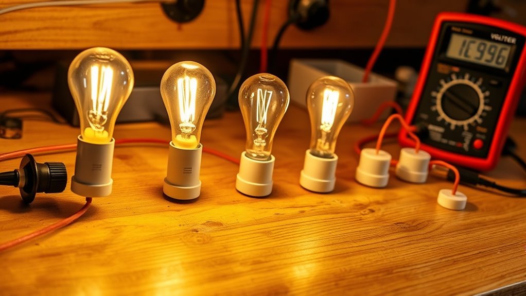
When you explore series circuits, you’ll find that they create a single path for current to flow by connecting components end-to-end. Each element is connected in series, meaning the same current passes through every part, which is essential for understanding how these circuits function.
This arrangement guarantees that if one component fails, the entire circuit stops working, as there’s no alternative path for the current.
In these circuits, the total voltage is divided among the components. Each component experiences a voltage drop according to its resistance. Consequently, the total resistance is simply the sum of the individual resistances, resulting in a greater overall resistance.
Characteristics of Series Circuits
Although series circuits might seem straightforward, their unique characteristics have a significant impact on electrical systems.
In a series circuit, components are connected end-to-end, creating a single path for the current to flow. This means the current stays consistent through each element. However, the voltage is divided among the components, with each one getting a portion proportional to its resistance.
Every component shares a single electrical node with its neighbor, ensuring a seamless current path. The total resistance of a series circuit is simply the sum of all individual resistances. This makes the circuit more resistant overall, which can affect performance.
An example of this is a chain of resistors, where the total voltage is split across each resistor based on its resistance.
Overview of Parallel Circuits
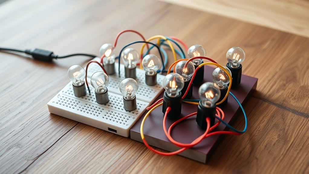
Unlike series circuits, parallel circuits offer distinct advantages due to their unique configuration.
In a parallel circuit, components are connected across the same two points, creating multiple paths for current to flow. This setup ensures that each element experiences the same voltage, resulting in identical voltage drops across all of them.
One of the significant benefits is that the total current is the sum of the individual currents through each branch, allowing for more current than would be possible through a single path. Plus, the total resistance is lower than the smallest resistor in the circuit, calculated using the formula 1/R_total = 1/R1 + 1/R2 + … + 1/Rn.
If one component fails, others remain operational, keeping the circuit functional. This reliability makes parallel circuits highly efficient and versatile.
Characteristics of Parallel Circuits
Parallel circuits exhibit unique characteristics that distinguish them from series circuits. In a parallel setup, you connect each component across the same two points, creating multiple paths for current flow. This design ensures that the voltage across each element remains constant, matching the voltage of the power source.
Unlike series circuits, if one component in a parallel circuit fails, the others continue to operate independently, maintaining the circuit’s overall functionality.
In parallel circuits, a single component’s failure doesn’t disrupt the entire system’s operation.
The total current in a parallel circuit equals the sum of currents through each branch. When it comes to resistance, you calculate the total resistance using the formula 1/R_total = 1/R1 + 1/R2 + …, resulting in a total resistance that’s lower than the resistance of the smallest resistor in the circuit.
This characteristic enhances the circuit’s efficiency and reliability.
Comparing Series and Parallel Circuit Configurations

When comparing series and parallel circuit configurations, you’ll notice distinct differences in how they handle current flow.
Series circuits route current through a single path, causing voltage to divide across the components, while parallel circuits offer multiple pathways, maintaining a consistent voltage.
Additionally, calculating resistance differs; with series circuits, resistances are added, and in parallel circuits, a reciprocal formula is used to determine a lower total resistance.
Current Flow Pathways
In the domain of electrical circuits, understanding the pathways for current flow is essential.
In series circuits, components are linked end-to-end, allowing current to flow through a single path. This means:
- The same current goes through all components.
- Any break in the path stops the entire current flow.
- The total resistance increases, affecting the current.
- Components share the total voltage supply.
In contrast, parallel circuits offer multiple paths for current. Components connect across common points, ensuring:
- The current divides among the branches.
- Any break in one path doesn’t affect the others.
- The total resistance decreases, often to a value less than that of any individual resistor.
- Each component receives the same voltage as the source.
Understanding these pathways enables you to design and troubleshoot circuits effectively.
Component Voltage Distribution
Although series and parallel circuits both distribute voltage, they do so in fundamentally different ways.
In a series circuit, the component voltage distribution is such that the total voltage from the source is divided among the components. Each component experiences a voltage drop proportional to its resistance. For instance, if you have a series circuit with resistors experiencing 2V, 3V, and 1V, the total voltage provided by the battery is 6V.
Conversely, in a parallel circuit, the voltage distribution across the components remains consistent. Each component receives the full source voltage, regardless of individual resistance. So, if you connect three resistors to a 12V battery in parallel, each resistor will have 12V across it.
This uniform distribution sets parallel circuits apart from their series counterparts.
Resistance Calculation Methods
Calculating resistance in series and parallel circuits involves distinct approaches that highlight their unique properties. Understanding these resistance calculation methods is essential for analyzing circuit behavior.
In a series circuit, add the resistances together: R_total = R1 + R2 + R3. This increases the overall resistance.
Conversely, in a parallel circuit, use the formula: 1/R_total = 1/R1 + 1/R2 + 1/R3. This results in a total resistance that is lower than the resistance of the smallest resistor in the circuit.
Here’s a quick comparison:
- Series Circuit: Sum the resistances for the total.
- Parallel Circuit: Use reciprocals for total resistance.
- Series: Total resistance increases with the addition of more resistors.
- Parallel: Total resistance decreases with more resistors.
These methods reveal how circuit configurations affect resistance.
Voltage and Current in Series Circuits

When you explore the characteristics of series circuits, it’s essential to understand how voltage and current behave.
In a series circuit, the current flows uniformly through each component in sequence. No matter how many resistors you add, the current remains constant throughout the circuit. This is a defining feature that distinguishes series circuits from other types.
However, voltage behaves differently. The total voltage supplied to the circuit is divided among the components. Each component experiences a voltage drop that depends on its resistance.
In a series circuit, voltage is divided among components, with each experiencing a drop based on its resistance.
For instance, if you have a 12-volt series circuit with three equal resistors, each will have a 4-volt drop.
Voltage and Current in Parallel Circuits
In a parallel circuit, you’ll notice that the voltage across each component matches the source voltage, ensuring consistency throughout the circuit.
The total current is the sum of the individual currents passing through each branch, which differs based on the branch’s resistance.
To find the total resistance, use the formula 1/R_total = 1/R1 + 1/R2 + … + 1/Rn, resulting in a resistance lower than the smallest individual resistor.
Voltage Consistency Across Components
Although circuits can be designed in various configurations, parallel circuits offer the advantage of maintaining a consistent voltage across each component. When components are connected in parallel, each one receives the same voltage as the source. This means:
- Each component experiences an equal voltage drop, ensuring uniformity.
- The total voltage remains constant regardless of the number of components added.
- Components operate independently; if one fails, the others continue to work.
- A voltmeter should be connected in parallel for accurate voltage readings.
For instance, if three resistors are connected in parallel across a 12-volt battery, each resistor receives 12 volts, regardless of its resistance.
This setup enables reliable operation and simplifies troubleshooting, as issues can be isolated without affecting the entire circuit.
Current Distribution Among Branches
Parallel circuits not only maintain a consistent voltage across components but also manage current distribution efficiently. Each component in a parallel circuit receives the same voltage, ensuring uniform electrical potential.
However, the current flowing through each branch varies based on the branch’s resistance. You’ll see that the total current flowing through the circuit equals the sum of the currents in each branch, as guided by Kirchhoff’s current law. This characteristic allows parallel circuits to handle multiple paths for current, optimizing the flow.
A unique feature of parallel circuits is that the total resistance is less than the sum of the individual resistors. This design enables current to flow more easily, distributing itself effectively and enhancing circuit performance without requiring any complex calculations on your end.
Total Resistance Calculation Method
When calculating total resistance in parallel circuits, it’s essential to understand how the resistors interact. The total resistance calculation method involves using the formula: ( frac{1}{R_{text{total}}} = frac{1}{R_1} + frac{1}{R_2} + frac{1}{R_3} + ldots ), where each ( R ) represents an individual resistor.
This method highlights that:
- The total resistance is always less than the resistance of the smallest resistor in the circuit.
- Adding resistors in parallel decreases the overall resistance.
- Each component experiences the same voltage, equal to the power supply’s voltage.
- Total current is the sum of the currents through each branch.
For example, with resistors of 4 ohms and 6 ohms in parallel, the total resistance is calculated as ( R_{text{total}} = frac{1}{left(frac{1}{4} + frac{1}{6}right)} = 2.4 ) ohms.
Resistance in Series vs. Parallel Circuits
Understanding how resistance behaves in series vs. parallel circuits is essential for anyone working with electrical systems.
In a series circuit, the resistance of each component is added together, resulting in a total resistance that is higher than the individual resistances. This increased resistance reduces the current flowing through the circuit, as stated by Ohm’s Law. With more components, you’ll notice a greater voltage drop across each one.
On the other hand, in parallel circuits, the total resistance is less than the sum of the individual resistors. You calculate it using the formula 1/R_total = 1/R1 + 1/R2 + 1/R3.
This configuration maintains a constant voltage across each component, equal to the source voltage. With reduced resistance, the current increases, and it divides among the branches based on each resistor’s resistance.
Practical Applications and Examples

Though series and parallel circuits each have unique characteristics, their practical applications highlight their strengths in everyday use.
Series circuits are useful for situations where you want a simple design and dimming effects, like string lights. However, a single burned-out bulb can interrupt the entire circuit.
Parallel circuits, on the other hand, are more reliable for household wiring. If one device fails, the others continue to function. This makes them ideal for homes and power distribution systems.
Here are some practical examples:
- Holiday Lights: Series circuits allow for a uniform dimming effect.
- Household Wiring: Parallel circuits guarantee all appliances can function independently.
- Power Distribution: Parallel circuits minimize resistance and support high-power devices.
- Device Voltage: Series circuits effectively distribute voltage, making them suitable for specific applications.
Conclusion
When you’re choosing between series and parallel circuits, consider their unique advantages. Series circuits offer simplicity and are great for low-cost applications, but any failure affects the whole system. Parallel circuits, on the other hand, provide reliability because each component operates independently. You’ll find that parallel circuits are more efficient for most practical applications, as they guarantee a consistent voltage across components. Ultimately, your decision should reflect the specific needs and constraints of your electrical system.
FAQs
1. What Are the 5 Differences Between Series and Parallel Circuits?
You’re exploring the differences between series and parallel circuits. In series, the current is constant, the paths are singular, and the resistances add up. In parallel, the voltage remains constant, the current divides, and the paths remain functional even if one fails.
2. What Is the Difference Between Serial and Parallel Connection?
In a serial connection, data or signals travel sequentially, one after another. In a parallel connection, data or signals move simultaneously across multiple channels. Choose serial for simplicity and parallel for speed and efficiency.
3. What Is the Difference Between Parallel and Series Circuits?
When comparing parallel and series circuits, parallel circuits allow multiple paths for current, maintaining a constant voltage across components. In sequence circuits, there’s a single path, meaning voltage divides among components, affecting performance differently.
4. What Is the Difference Between the Two Types of Circuits?
You should be aware that the primary difference lies in the current paths. Series circuits have one path, so a single failure stops everything. Parallel circuits offer multiple paths, ensuring that other components continue to function even if one fails.
