

Types of Comparator: Exploring Variations for Precise Comparisons
Making precise and accurate comparisons is a signal analysis and electronic systems cornerstone. To achieve this, a profound comprehension of various comparator types becomes indispensable. These comparators, designed to evaluate signals differing in frequencies, amplitudes, and electronic traits, play a pivotal role in ascertaining relationships and relative values between signals. By delving into the distinct categories of these linear and nonlinear comparators, one can glean valuable insights into their individual functionalities, applications, and inherent advantages. These devices find their crucial utility within static relays, where they compare multiple inputs and deliver outputs based on these comparisons. This exploration of comparator variations illuminates their critical significance in many technological applications.
Comparators in Signal Analysis and Static Relays
When making precise and accurate comparisons, a solid understanding of the various types of comparators — devices that compare signals of differing frequencies, amplitudes, and electronic characteristics — is essential. These linear or nonlinear comparators are pivotal in determining the relationship or relative values of the signals they evaluate. Examining these different comparators gives you valuable insights into their unique functionalities, applications, and advantages. Each comparator’s use in assessing electronic signals, whether they bear differing frequencies or amplitudes, underscores their significant role in various technological applications.
The comparator is part of a static relay, which receives two or more inputs to be compared and gives output based on the comparison.
Exploring the Different Types of Comparators
The various types of comparators are;
- Amplitude Comparator
- Phase Comparator
- Hybrid Comparator
Amplitude Comparator
An amplitude comparator compares the magnitude of two input quantities irrespective of the angle between them. One of the inputs is the operating quantity, and the other is a restraining quantity.
When the amplitude of the operating quantity exceeds that of the restraining portion, the relay sends a tripping signal to the circuit breaker.
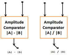
- The Amplitude comparator compares two vectors, |A| and |B|
- Gives an output: the algebraic difference between the magnitudes |A| and |B|
- Output is +ve, if |A| > |B|
- Output is –ve, if |A| < |B|
- Output is zero, if |A| = |B|
Comparison by the ratio:
- Output is >1, if |A| > |B|
- Output <1, if |A| < |B|
- Output is Zero if |A| is zero.
Amplitude types of the comparator.
-
Integrating comparator
-
Instantaneous comparator
-
Sampling Comparator
Integrating Comparator
- Circulating Current Type
- Opposed Voltage Type
Circulating Current Type

It can also be used as an impedance relay. Two rectifier bridges can be arranged in such a manner, as shown in the figure below, to function as amplitude comparator circulating type.
The po/2016/07/distance-protection-impedance-relay operates when S1>S2 where S1=K1i1 and S2 = K2i2. This arrangement gives a sensitive relay whose voltage may be represented in the VI characteristic of the figure.
Opposed Voltage type
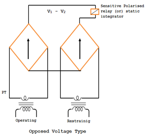
This type works with voltage input signals derived from PTs. The operation depends on the average rectified voltage (V1-V2) difference. Here, the rectifiers are not protected against higher currents. The relay operates when V1 >V2.
Instantaneous Comparator
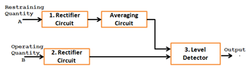
The restraining signal is rectified and smoothed completely to provide a level restraint.
This is then compared with the peak value of an operating signal, which may or may not be rectified but is smoothened. The tripping signal is provided if the operating signal exceeds the level of the restraint. The block diagram is shown in the figure above. Since this method involves smoothening, the operation is slow. A faster way is phase splitting the wave shapes of instantaneous amplitude comparator are shown in fig below before rectification and the averaging circuit can be eliminated.

Sampling Comparator
It is specifically designed for use in sample-and-hold circuits or track-and-hold circuits. A sampling comparator is a specialized type used in systems that require the sampling and holding of analog signals. Its main purpose is to accurately capture the instantaneous value of an input signal during the sampling phase and maintain that value during the holding phase. Sampling comparators are commonly used in various applications, including:
- Analog-to-digital converters (ADCs)
- Sample-and-Hold Circuits
- Time-Interleaved ADCs
Features & Characteristics
Key features and characteristics of a sampling comparator include:
Fast Response: Sampling comparators are designed to have a fast response time. They must settle quickly to the input signal level during sampling to capture the accurate voltage value.
Low Offset Voltage: Offset voltage is the voltage difference required at the inputs of a comparator to make its output change state. In sampling comparators, minimizing the offset voltage is crucial to accurately sampling and holding the input signal.
Low Drift: Drift refers to the change in offset voltage over time or with temperature variations. Low drift is desirable in sampling comparators to maintain the accuracy of the sampled value during the holding period.
High Input Impedance: Sampling comparators typically have a high input impedance to minimize the loading effect on the input signal during the sampling phase. This ensures that the comparator’s input impedance does not significantly affect the sampled value.
High Open-Loop Gain: A high open-loop gain allows the comparator to respond quickly to small voltage differences between the input signal and the held voltage during the holding phase. This helps maintain the accuracy of the stored value.
Phase Comparator
The phase comparison technique is widely used for all practical directional, distance, differential, and carrier relays.
If the two input signals are S1 and S2, the output occurs when the inputs have a phase relationship within the specified limits.
Both the input must exist for the output to occur. The operation is independent of their magnitudes and is dependent only on their phase relationship. The figures below show that the phase comparator is a simple form. The function is defined by the boundary of marginal operation and represented by the straight lines from the origin of the S-plane.
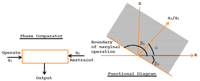
The condition of operation is β1< θ < β2.
θ is the angle by which S2 lands S1. If β1 = β2 =90o, the comparator is called a cosine comparator, and if β1=0 and β2=180o, it is a sine comparator.
In short, a phase comparator compares two input quantities in phase angle (vertically) irrespective of the magnitude and operates if the phase angle between them is < 90.
There are two types of phase comparators:
-
Vector product comparator
-
Coincidence type phase comparator.
Vector Product comparator
This comparator recognizes the vector product or division between two or more quantities. Thus, the output is A, B, or A/B.
Coincidence Comparator
Consider two signals, S1 and S2. The period of Coincidence of S1 and S2 will depend on the phase difference between S1 and S2. The fig below shows the coincidence of S1 and S2 when S2 lags S1 by less than π/2, i.e., θ.
The period of coincidence of S1 and S2 with a phase difference of θ is Ψ = 180o – θ. Different techniques are used to measure the period of coincidence. Two of the important types are
- Bloke Spike Method (Direct Phase Comparison)
- Coincidence type – Integrating phase comparator
Hybrid Comparator
This kind of comparator compares the input quantities’ magnitude and phase. Hence, this type is a mixed version.
In the hybrid comparator, both amplitude and phase comparators are used. Inputs are given to a phase comparator. The output of the phase comparator is given to the amplitude comparator.
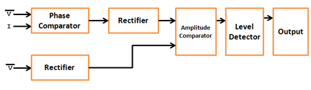
Static impedance relays comparing V and I are generally Hybrid Comparators.
Level Detector
The level detector determines the level of its input concerning a predetermined setting.
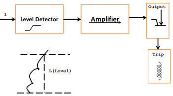
When input I exceeds the level (L) and the level detectors’ output (O) exceeds, the relay’s output stage gets a triggering signal via an amplifier.
Conclusion
In conclusion, comparators are essential for precise measurements and comparisons in various industries. They come in different types like voltage comparators, window comparators, and analog-to-digital converters, each tailored to specific needs. Choosing the right comparator depends on the application. Understanding these types empowers engineers to make informed decisions for optimal performance. As technology advances, we can expect more efficient and advanced comparator solutions for accurate measurements and comparisons in diverse applications.
FAQs
What are Amplitude and Phase Comparators, and how do they work?
Amplitude and Phase Comparators are devices used to compare signal amplitudes and phases. They analyze waveforms with a phase detector, determining the phase relationship and magnitude between input and reference signals.
What are the key components and benefits of Amplitude Comparators?
Amplitude Comparators consist of essential components like “top” for faster responses and “spectrum” to analyze frequency components, offering accurate results in digital systems.
How do Amplitude and Phase Comparators contribute to signal analysis?
They use samples from input signals in control loops and expressions, providing valuable information for precise signal analysis in digital systems.
What are the advantages of using Amplitude and Phase Comparators in engineering?
Amplitude Comparators offer straightforward signal magnitude comparison, identifying if signals fall within a specified range and assessing the possibility of signs being in or out of phase.
How do Amplitude and Phase Comparators impact system cost and space efficiency?
By using cost-effective devices and optimizing designs, engineers can reduce costs and save space while maintaining accuracy in the system.
