

What Is Cycloconverter? Working, Types, and Applications
You’ve probably heard of devices that change electricity from one form to another, but have you ever wondered how you can directly convert AC power from one frequency to another? That’s where cycloconverters come into play. They work without an intermediate DC link and have unique applications in high-power settings. Curious about how they operate and the technology behind them? There’s a lot more to explore in their operation and benefits.
Definition of Cycloconverter
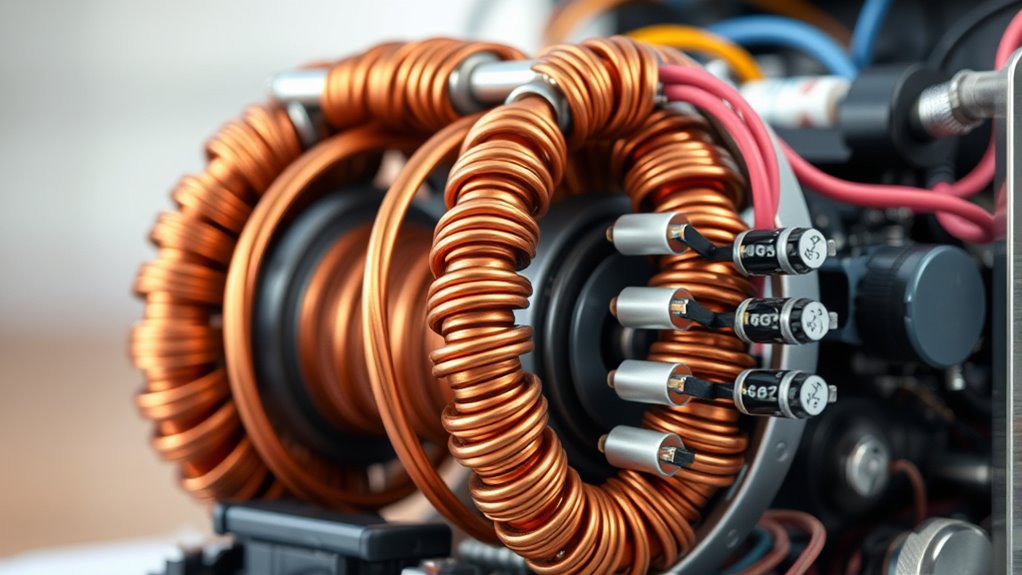
A cycloconverter, though often complex in its operation, fundamentally serves as a power electronic device designed to convert AC power from one frequency to another without using an intermediate DC link. Cycloconverters are particularly useful in high-power applications where smooth output frequency and voltage control are essential. This is achieved by synthesizing the output waveform through controlled semiconductor switches, like thyristors, which select segments of the input AC waveform. By doing so, they can effectively manage the output frequency, making them ideal for large motor drives and industrial processes. Cycloconverters come in various configurations, including single-phase to single-phase and three-phase to three-phase, allowing for step-up and step-down conversion to suit different power needs.
Operation Principle
When you explore the operation principle of a cycloconverter, you’ll see how it synthesizes the output waveform by selecting segments of the input AC using semiconductor switches like thyristors. By adjusting the firing angles of these thyristors, you can control the output frequency independently from the voltage. Cycloconverters operate in rectification and inversion modes, allowing for variable frequency output by generating either positive or negative voltage cycles.
Synthesizing Output Waveform
Cycloconverters play a pivotal role in synthesizing the output waveform by skillfully selecting segments of the input AC voltage. This is achieved using controlled semiconductor switches, like thyristors, which alternate between positive and negative converters. Doing so creates positive and negative half cycles of the output waveforms, resulting in a continuous AC output. You can control the output voltage and frequency by adjusting the firing angles of the thyristors. This adjustment allows for the precise shaping of the output waveform. The output frequency is varied by timing the switching cycles, producing a stepped output that matches your desired frequency. Additionally, advanced techniques such as Pulse Width Modulation (PWM) can enhance waveform quality and reduce harmonic distortion.
Firing Angle Control
Although often overlooked, firing angle control is fundamental in the operation of cyclo converters, as it dictates the timing at which the thyristors are triggered. Adjusting firing angles can directly influence the output voltage and frequency, allowing precise motor speed control and enhancing the quality of the output waveform.
Here’s how you can optimize the performance of a cycloconverter:
- Vary Firing Angles: Adjust the angles to modulate the RMS value of the output voltage.
- Alternate Half-Cycles: Set firing angles to alternate between positive and negative cycles for waveform synthesis.
- Manage Output Frequency: Fine-tune firing angles to achieve the desired frequency conversion ratio.
- Employ Control Strategies: Use phase control and PWM techniques to reduce harmonic distortion and improve waveform quality.
Rectification and Inversion
As you delve into the operation principle of cycloconverters, it’s essential to understand the dual processes of rectification and inversion that define their functionality. Cycloconverters work by rectifying the input AC voltage during the positive half-cycle and then inverting it during the negative half-cycle. This process synthesizes the output waveform by piecing together segments of the input waveform. By controlling the firing angles of thyristors, you can independently regulate both output voltage and frequency. In rectification mode, the positive converter generates an output voltage for positive load current, while in inversion mode, the negative converter handles negative load current. Adjusting the thyristor conduction duration allows you to fine-tune the output waveform frequency, achieving variable outputs without an intermediate DC link and optimizing efficiency.
Types of Cycloconverters
When exploring types of cycloconverters, you’ll encounter the blocking mode and circulating current types. In blocking mode, only one converter is active at any time, simplifying control but limiting flexibility. Conversely, circulating current cycloconverters have both converters operating simultaneously, offering more dynamic performance but requiring careful management of circulating currents.
Blocking Mode Characteristics
Blocking mode cycloconverters efficiently manage voltage and frequency by operating one converter at a time. This approach uses a positive converter for positive load currents and a negative converter for negative ones, eliminating the need for intergroup reactors. The output frequency is typically lower than the input, making blocking mode ideal for applications needing variable AC power. Here’s why you might consider them:
- Compact Design: The lack of intergroup reactors makes the setup more compact and cost-effective.
- Smooth Control: The controlled firing of thyristors ensures smooth voltage and frequency adjustments.
- Application Versatility: Perfect for cement mills, rolling mills, and large motor drives.
- Efficient Operation: They deliver full torque at low speeds, enhancing performance in demanding environments.
Circulating Current Dynamics
Although circulating current cyclo converters add complexity to the system, their ability to operate both positive and negative converters simultaneously makes them indispensable for high-power applications. They’re crucial in environments where effective frequency conversion is needed, such as large industrial drives in rolling mills and cement plants. These converters manage circulating current with intergroup reactors, preventing short circuits and ensuring stable operation.
Whether configured as step-up or step-down, they offer flexibility in managing output frequency. Step-up types provide a higher output frequency than the input, while step-down types offer a lower frequency. Typically, the output/input frequency ratio is less than one-half. This feature is particularly useful in high-power settings, allowing these cyclo converters to handle substantial power loads efficiently.
Key Components
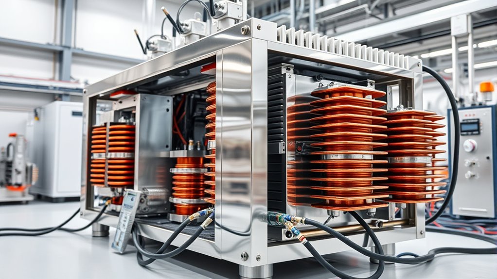
Cycloconverters are fascinating devices that leverage controlled rectifiers, like thyristors, to convert AC power efficiently from one frequency to another without needing an intermediate DC link. You’ll find that the key components of a cycloconverter include the positive converter (Conv-P) and the negative converter (Conv-N). These converters work back-to-back to synthesize the desired output waveform. By adjusting the firing angles of the thyristors, each converter independently controls the output voltage and frequency. Here are some essential aspects to consider:
- Positive Converter (Conv-P): Manages positive half-cycles.
- Negative Converter (Conv-N): This handles negative half-cycles.
- Thyristors enable precise control over power conversion.
- Advanced Switching Devices: IGBTs enhance performance in high-power applications.
Control Mechanisms
Having explored the fundamental components of cycloconverters, it’s important to understand how these elements interact through sophisticated control mechanisms. You can manage the output voltage and frequency by employing phase-controlled strategies, which involve adjusting the firing angles of thyristors. This ensures a smooth control of the output waveform. Advanced techniques like Pulse-Width Modulation (PWM) help reduce harmonic distortion, enhancing the power quality of the output. With vector control methods, you can convert three-phase AC into a two-dimensional vector, effectively managing output conditions and improving dynamic performance. Direct Torque Control (DTC) further enhances your ability to efficiently manipulate motor torque and flux. However, the complexity of these control systems demands sophisticated algorithms and real-time processing for optimal operation.
Applications in Industry
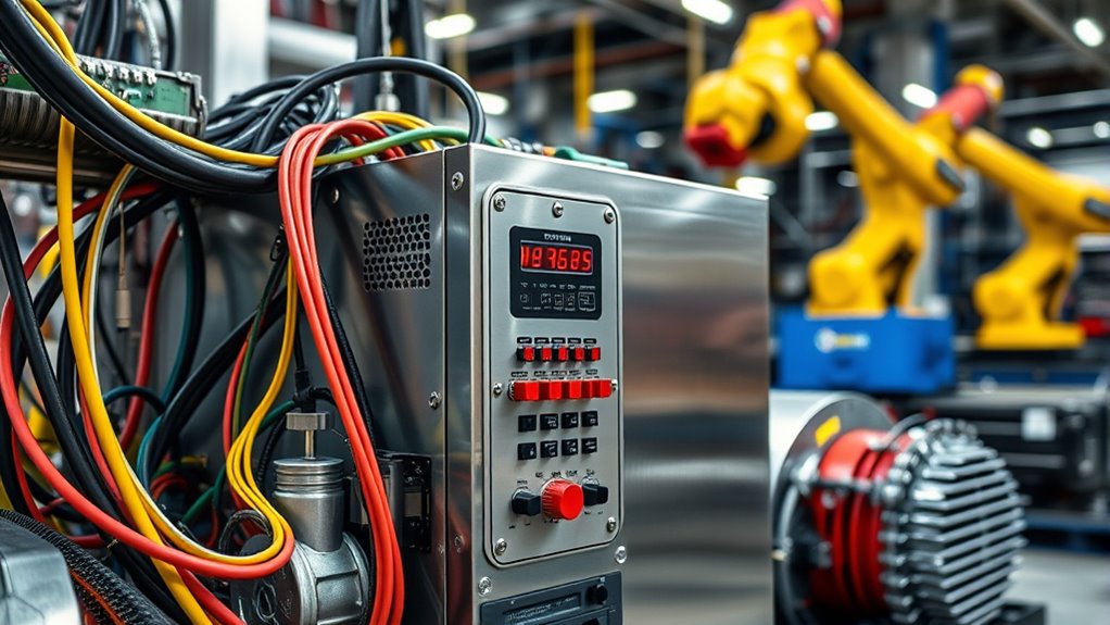
Looking at modern industrial operations, you’ll find cycloconverters crucial in optimizing performance across various sectors. These devices are indispensable for achieving variable speed control and efficient power management in systems with large motors. Consider these applications:
- Cement Mills: Cycloconverters control large motors’ speed during grinding, ensuring efficient operation.
- Steel Industry: They provide variable speed control in rolling mill motors, boosting productivity and flexibility in hot-rolling.
- Marine Vessels: Cycloconverters enable smooth acceleration and deceleration, which are crucial for ship propulsion, especially during low-speed maneuvers.
- Mining Applications: These converters allow large horsepower motors to start directly under full load, which is vital for winders and hoists.
Railway systems enhance power conversion, supporting electric trains at specific frequencies.
Advantages and Limitations
Exploring the various industrial applications reveals that optimizing motor control is key to enhancing efficiency and performance. Cycloconverters offer several advantages, such as high efficiency by eliminating the need for an intermediate DC link. This simplification reduces energy losses and provides smooth speed control with minimal torque ripple. The compact design is another benefit due to the absence of energy storage components. However, the use of numerous semiconductor switches can increase system complexity.
A significant limitation is the generation of harmonics in the output waveforms, which can negatively impact power quality. Additionally, cycloconverters face challenges with commutation at higher output frequencies, especially in step-up configurations, making them less suitable for certain applications. Addressing these limitations is crucial for effective implementation.
Harmonic Generation and Mitigation

When using cycloconverters, you will likely encounter harmonics that impact output waveform quality and overall system performance. Carmonic control techniques like filters and advanced methods like Pulse Width Modulation (PWM) are used to manage these issues. Should be considered. These strategies can significantly reduce harmonic distortion and enhance power quality, aligning with standards like IEEE Std 519.
Output Waveform Quality
How do cycloconverters affect the quality of output waveforms? Cycloconverters can cause harmonic distortion, impacting output waveform quality. Here’s how:
- Harmonic Generation: Cycloconverters generate current and voltage harmonics due to the pulse number. This can lead to waveform distortion, impacting overall performance.
- Waveform Degradation: Harmonic distortion reduces power quality, potentially causing inefficiencies in your electrical systems.
- Harmonic Filtering: Proper harmonic filtering is crucial. It helps ensure compliance with standards like IEEE Std 519 and maintains acceptable power quality.
- Advanced Strategies: Advanced control strategies, such as Pulse Width Modulation (PWM), can reduce harmonic content and enhance output waveform quality.
Harmonic Control Techniques
Addressing the quality of output waveforms in cycloconverters naturally leads to exploring harmonic control techniques, as harmonics significantly impact performance. Cycloconverters generate harmonics, defined by the equation ±1) ± 6, which can cause power quality issues. Harmonic control is essential to maintain power quality and ensure reliable operation of connected equipment. Excessive Total Harmonic Distortion (THD) can degrade performance, making mitigation vital. Techniques such as low-pass filters, active filters, and advanced strategies like Pulse Width Modulation (PWM) effectively reduce harmonic content. These methods help adhere to standards like IEEE Std 519 (1992), ensuring harmonics remain within acceptable limits. Controlling harmonics improves both the efficiency and reliability of your cycloconverter applications.
Comparison With Other Converters
While cycloconverters offer a unique approach to frequency conversion by directly converting AC power without an intermediate DC link, they stand apart from other PWM converters requiring a DC stage. Cycloconverters excel in AC-to-AC conversion for applications needing lower output frequencies. However, their output waveform has high total harmonic distortion (THD), unlike matrix converters that achieve lower THD through bi-directional switching.
Here’s a comparison to consider:
- Cycloconverters: Direct AC to AC conversion with simplicity but higher THD.
- Matrix Converters: Lower THD with complex switching.
- PWM Converters Require an intermediate DC stage; they are good for precise control.
- SCR-Controlled Converters: They have a similar simplicity but need a DC link, unlike cycloconverters.
Choose based on your application needs and complexity tolerance.
Future Trends and Innovations
As the field of power electronics advances, cycloconverters are poised to undergo significant transformations. You’ll soon see innovations focusing on advanced materials like silicon carbide (SiC) and gallium nitride (GaN) transistors, which promise higher efficiency and easier thermal management. Improving control strategies using model predictive control and artificial intelligence will make cycloconverters more adaptable in dynamic settings. The development of multilevel cycloconverters is also on the rise, enhancing output waveform quality and reducing harmonic distortion. With renewable energy systems gaining prominence, cycloconverters will be key in grid integration, aiding efficient frequency conversion for wind and solar applications. Hybrid systems combining cycloconverters with energy storage technologies like batteries or supercapacitors will bolster power supply stability for electric traction and variable speed drives.
Conclusion
In exploring cyclo converters, you’ve seen how they efficiently convert AC power to different frequencies without needing a DC link. Their ability to control output voltage and frequency smoothly makes them perfect for high-power applications like the cement and steel industries. Despite some limitations, such as harmonic generation, their advantages outweigh the drawbacks. Compared to other converters, cyclo converters offer unique benefits. You can expect even more innovations as technology advances, enhancing their performance and expanding their applications.
FAQs
1. What Is Meant by Cycloconverter?
You’re asking about cycloconverters. These devices change AC power from one frequency to another directly. They don’t need an intermediate DC link and are used in industries for high-power applications requiring precise frequency and voltage control.
2. What Is the Difference Between Inverter and Cycloconverter?
Inverters convert DC to AC, while cyclo converters directly change AC frequencies. Inverters use transistors to control output, reducing harmonics. Cycloconverters handle high-power applications but can introduce more harmonic distortion due to thyristor use.
3. What Are the Applications of Cycloconverter?
You’re looking at cycloconverter applications in various industries. You’ll find them in cement mills, steel hot-rolling, marine propulsion, electric traction for trains, and pumped hydro storage, providing precise speed, torque control, and efficient energy management.
4. What Are the Two Types of Cycloconverters?
There are two types of cyclo converters: Blocking Mode and Circulating Current. Blocking Mode is simpler and cheaper, ideal for cost-sensitive applications. Circulating Current uses both converters but requires additional components to handle higher power needs.
