

Scr Electronic – Advanced Electronics for Your Needs
You might find it interesting how Silicon-Controlled Rectifiers (SCRs) are pivotal in managing power control applications due to their unidirectional switching nature. Applying a gate signal lets you control the current flow between the anode and cathode, allowing precise regulation in various devices. SCRs operate in three distinct modes—forward blocking, reverse blocking, and forward conduction—each critical for efficient power management. Are you curious about the various ways to trigger these devices or the differences between SCRs and TRIACs? Let’s explore how these components can transform your electronic projects and power systems.
Key Takeaways
- SCRs control high-power AC applications like motor speed regulation and industrial machinery.
- SCRs have three terminals: anode, cathode, and gate, and conduct current in one direction.
- SCRs operate in three modes: forward blocking, reverse blocking, and forward conduction.
- SCRs can be turned on using gate, thermal, and light-triggering methods.
- SCRs offer robust and reliable performance in power converters, voltage regulators, and welding machines.
Understanding SCR Basics

Silicon-controlled rectifiers, known as SCRs, are fundamental components in power control applications.
SCRs, or four-layer semiconductor devices, are indispensable when controlling high power and voltage. These unidirectional devices act as electronic switches, making them essential in various industries, such as motor control, lighting dimming, and power regulation.
SCRs have three terminals: the anode, cathode, and gate.
A gate signal is applied to cause an SCR to conduct current. Once the gate receives this signal, the SCR conducts current from the anode to the cathode. This conduction continues until the current drops below a certain threshold.
What’s unique about SCRs is that they only conduct in a forward direction, meaning current flows from the anode to the cathode, not in reverse.
Modes of SCR Operation
Now, let’s explore the three main modes of SCR operation: forward blocking mode, forward conduction mode, and reverse blocking mode.
In forward blocking mode, the SCR is off with a small leakage current due to junction J2 being reverse-biased.
Forward conduction mode kicks in when a positive gate pulse latches the SCR on, while reverse blocking mode occurs when the anode and cathode voltages are reversed, acting like two diodes in series.
Forward Blocking Mode
In the forward blocking mode of SCR operation, the anode is positive, the gate has zero voltage, and the cathode is negative. Junctions J1 and J3 are forward-biased during this mode, while junction J2 is reverse-biased. This configuration means that even though the SCR is in the forward blocking mode, only a small leakage current can flow through the device.
In this mode of SCR operation, the SCR is essentially in its off state, preventing significant current from passing through. Despite this, a small leakage current does exist due to the reverse-biased junction J2.
If the voltage across the SCR increases to the reverse breakdown voltage at junctions J1 and J3, it can cause an avalanche breakdown, leading to a sudden and uncontrolled increase in current.
Understanding the forward blocking mode of SCR is important for managing current flow in power electronics applications. Even when the anode is positive, the device remains off, allowing you to control when it will conduct electricity.
The forward blocking mode guarantees that the SCR doesn’t conduct unintentionally, providing vital control over the circuit’s behavior.
Reverse Blocking Mode
The reverse blocking mode of SCR operation occurs when the anode is negative, and the cathode is positive, preventing current flow through the device. In this mode, SCRs act like two diodes in series with junctions J1 and J3 forward-biased and J2 reverse-biased. This configuration guarantees minimal reverse current, showcasing the SCR’s reverse blocking capability.
When a reverse voltage is applied, the SCR’s ability to block this voltage is essential. A reverse breakdown can occur if the reverse voltage exceeds a certain threshold. This breakdown happens at junctions J1 and J3, leading to an avalanche effect that may damage the device if not properly managed.
The SCR must have a strong reverse-blocking capacity to prevent damage. This capacitive damage. This cap effectively helps the city handle reverse polarity conditions. The reverse blocking mode protects electronic circuits, ensuring they function correctly without being compromised by unwanted reverse currents.
An SCR may be combined with a reverse-conducting diode in some applications to enhance performance. This combination guarantees that the system can efficiently handle both forward and reverse voltage conditions, maintaining the reliability and longevity of the electronic components.
Forward Conduction Mode
While reverse blocking mode safeguards against unwanted reverse currents, forward conduction mode empowers the SCR to manage power flow actively. In this mode, you can trigger the Silicon Controlled Rectifiers (SCR) to conduct by applying a voltage increase or a positive pulse to the gate terminal. Once the SCR is in the on state, it continues to perform due to the latching current until the current flowing through it drops below a specific level. This feature makes SCRs essential in high voltage and high power applications, providing effective power regulation.
To turn off the SCR in forward conduction mode, you must reduce the current flow or short-circuit the anode and cathode terminals. This mode of SCR operation is vital for rectifiers and other electronic systems requiring precise control over power flow. When conducting, the forward voltage drop across the SCR must be considered, as it affects overall efficiency.
Here’s a quick overview of key aspects:
| Aspect | Description | Importance |
|---|---|---|
| Gate Current | Triggers the SCR to start conducting | Essential for initiating forward conduction |
| Latching Current | Keeps the SCR conducting until the current drops below it | Maintains SCR operation |
| Forward Voltage Drop | The voltage drop across SCR during conduction | Impacts efficiency in high-power applications |
Thyristor Turn-On Methods
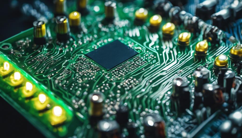
Activating a thyristor involves several distinct methods, each with a unique mechanism. One of the most common methods is gate triggering, in which a positive pulse is applied to the gate terminal to turn on the SCR. This method is highly controllable and widely used in various applications.
Another method is forward-voltage triggering, which involves applying a voltage across the anode and cathode. When this forward voltage exceeds a certain threshold, the thyristor turns on automatically.
Thermal triggering is another interesting method. It relies on an increase in temperature to activate the thyristor, which can be useful in environments with predictable and consistent temperature changes.
Light triggering uses photons to activate the SCR. When light hits the sensitive area of the thyristor, it generates electron-hole pairs, causing the device to turn on.
Temperature triggering is slightly different from thermal triggering. It involves using a change in temperature rather than just an absolute increase. This method is often incorporated into safety systems as it can react to sudden temperature changes.
Each turn-on method has advantages and applications, making thyristors versatile components in electronic circuits.
Simple SCR Circuit Design
Designing a simple SCR circuit starts with an AC voltage source connected to an SCR and a resistive load. The SCR, or Silicon Controlled Rectifier, remains forward-blocking until a gate current pulse is applied. This pulse is crucial for triggering the SCR into conduction. Once the SCR begins conduction, it allows current to flow through the load, effectively controlling the power applied to it.
In this circuit, the delay angle controls the SCR’s conduction. By adjusting when the gate pulse is applied within the AC cycle, you can control the duration of conduction and, consequently, the power delivered to the load. This principle is essential for applications requiring precise power control, such as lamp dimming or motor speed regulation.
When the current through the SCR becomes negative, the SCR stops conducting until a new gate pulse is applied. This cyclical triggering and conduction allow for efficient power regulation.
Applications of SCRs
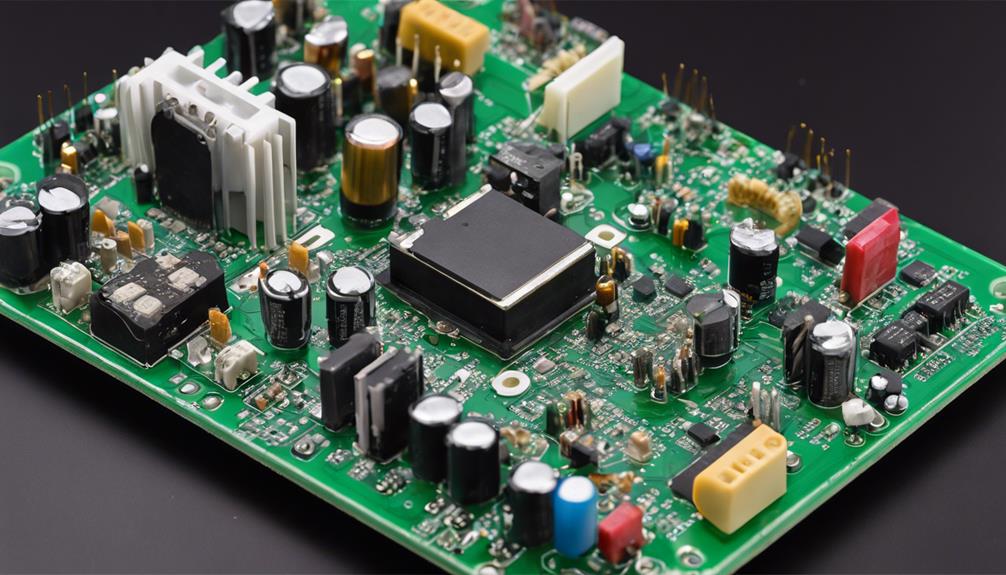
SCRs are the best components for controlling high-power AC because they are efficient and precise. They excel at motor speed regulation and provide exact control for various applications.
SCRs guarantee effective power management and reliable performance in industrial settings or consumer electronics.
High-Power AC Control
Silicon-controlled rectifiers (SCRs) are essential in high-power AC control applications because they regulate power precisely. SCRs are at the heart of various high-power systems, ensuring efficient and reliable performance.
In industrial machinery, SCR-based systems excel at motor speed control and heating element regulation, giving you the flexibility to fine-tune operations and save energy.
SCRs are also crucial in power converters and voltage regulators, as they easily handle the demands of high-voltage AC systems. Whether dealing with complex power transmission systems or everyday industrial tasks, these devices efficiently convert AC to high-voltage DC, which is vital for long-distance power delivery.
In welding machines and power supplies, SCRs offer robustness and reliability, ensuring continuous and stable power flow.
If you work with high-power lighting dimmers, SCRs provide the consistent performance needed for smooth operation. Their role in voltage regulation and power conversion cannot be overemphasized, making them a go-to choice for high-power AC control. With SCRs, you get precise control, enhancing your industrial equipment’s efficiency and longevity.
Motor Speed Regulation
Silicon-controlled rectifiers (SCRs) offer a versatile and efficient solution for controlling AC and DC motors. With SCRs, you can manipulate the firing angle to control the power delivered to the motor. This allows for precise speed regulation, making it perfect for applications that demand accurate speed control.
SCRs are widely used in industrial applications like conveyor belts, pumps, and fans, where reliable and cost-effective speed control is essential. By integrating SCRs into your control circuits, you can optimize energy consumption and extend the lifespan of your motors by avoiding sudden speed changes. This saves energy and reduces wear and tear on your equipment.
In motor and variable frequency drives, SCRs provide smooth and continuous speed control for various motor types. This flexibility makes them invaluable for a range of industrial uses.
Whether you’re dealing with AC or DC motors, SCRs can handle the job efficiently. So, if you want to improve motor speed regulation in your operations, consider SCRs’ benefits. They’re a smart choice for anyone aiming to achieve precise speed regulation and efficient energy use.
SCR vs. TRIACs
Many electronic applications require precise power control, and understanding the differences between SCRs and TRIACs is essential for choosing the right component.
SCRs, or Silicon Controlled Rectifiers, are unidirectional switches ideal for high-power and high-voltage applications. They conduct current in one direction, making them perfect for DC power control and switching tasks. You can trigger an SCR by injecting current into the gate or exceeding its breakover voltage.
On the other hand, TRIACs (Triode for Alternating Current) can conduct current in both directions, allowing for bidirectional current flow. This makes TRIACs highly suitable for AC power control applications such as lamp dimming and motor speed control. TRIACs have three terminals: gate, MT1, and MT2. Triggering methods for TRIACs involve applying a voltage signal to the gate terminal.
The key difference between SCRs and TRIACs is their ability to handle AC versus DC power. While SCRs excel in high-power and high-voltage applications, TRIACs are the go-to for AC applications due to their bidirectional current capabilities. Understanding these distinctions helps you select the right device for your power control needs.
Testing SCR Functionality

Understanding the basic differences between SCRs and TRIACs is only part of guaranteeing your application’s success. To confirm SCR functionality, you can start with a simple test using an ohmmeter. Check for continuity between the gate and cathode terminals. A functioning SCR should show continuity only when a small gate current is applied.
You can use practical testing circuits with a DC voltage source for more in-depth testing. This setup allows you to assess the SCR’s performance under real conditions. Connect the gate to a DC voltage source and observe whether the SCR conducts properly when triggered.
SCRs are significant in AC power control applications, providing precise power regulation. By integrating time-proportional power control, you can achieve efficient power management. This involves triggering the SCR at different points in the AC waveform to control the power delivered to the load.
Gate resistance is essential for proper SCR triggering. It influences the triggering thresholds and guarantees that the SCR delivers the correct amount of power. Testing the gate resistance can help you fine-tune the SCR’s performance for your application.
With these steps, you can confidently verify your SCR’s functionality and reliability.
Controlling SCR Triggering
Controlling SCR triggering is [VITAL] for precisely managing power in various applications. You can achieve this control through several methods: gate triggering, forward-voltage triggering, thermal triggering, light triggering, and temperature triggering. Each technique offers unique benefits depending on your specific needs.
You can use [DELAY ANGLE TUNING] to fine-tune when your SCR starts conducting. This technique allows you to deliver power precisely where and when needed. Complex circuits, often utilizing pulse transformers, are another option for specialized applications requiring precise SCR control.
Gate resistance also plays a [IMPORTANT] role. Adjusting the resistance can alter the triggering threshold, directly affecting the power delivered to your load.
For applications involving controlled bridge rectifiers, you’ll need to [VERIFY] simultaneous firing of SCRs in opposite pairs to maintain efficient power control.
Consider these key points when controlling SCR triggering:
- Gate resistance: Adjust it to change the triggering threshold.
- Delay angle tuning: Controls the start of SCR conduction.
- Pulse transformers: Used in complex circuits for precise triggering.
- Simultaneous firing: [NECESSARY] for controlled bridge rectifiers.
Conclusion
You’ve explored SCR electronics‘s core components and operational modes. Examined the different turn-on methods, simple circuit designs, and varied applications. Gained insights into efficient power management by comparing SCRs with TRIACs and learning how to test their functionality. Now, you’re equipped to control SCR triggering effectively, making you adept at leveraging these crucial components in your power control applications.
FAQs
1. What Is a SCR in Electronics?
You’re asking about SCRs in electronics? SCRs control power by acting as unidirectional switches. Their applications include motor control and lighting. They’re durable but need protection methods. Triggering methods and troubleshooting tips help manage their voltage and current ratings.
2. What Is the Function of SCR?
You control SCR operation by applying a signal to the gate drive. Due to their voltage and current ratings, SCRs excel in high-power applications. Advantages include efficiency and latching, but disadvantages involve triggering methods and protection needs.
3. Is SCR a DC or AC Switch?
An SCR can function as both a DC and AC switch. Its operation and applications include controlling power by chopping AC waveforms. Advantages include precise control, while disadvantages involve heat dissipation. Key characteristics are voltage and current ratings.
4. Is a SCR a Switch?
Yes, an SCR is a switch. In SCR applications, it functions by using SCR firing circuits and gate voltage. Unlike transistors, SCR characteristics include high voltage ratings. Triggering methods involve gate current, offering advantages and disadvantages.
