

Ripple Factor of Full Wave Rectifier: Formula & Calculation
When you explore the ripple factor of a full wave rectifier, you’re stepping into a world where AC meets DC with intriguing consequences. It’s not just about converting alternating current to direct current; the ripple factor quantifies the unwanted AC fluctuations in your supposedly smooth DC output. You might wonder why this matters, especially when powering sensitive electronics. Could optimizing this factor be the key to enhancing device performance and reliability? As you ponder this, consider how different rectifier designs might impact the ripple factor and what that means for your next project.
Key Takeaways
- The ripple factor for a full wave rectifier is approximately 0.48.
- A lower ripple factor indicates better DC output quality with fewer AC components.
- Full-wave rectifiers have a lower ripple factor compared to half-wave rectifiers.
- The ripple factor is crucial for designing efficient power supply units.
- Capacitors are used in rectifiers to reduce ripple and stabilize output.
Understanding Full Wave Rectifiers
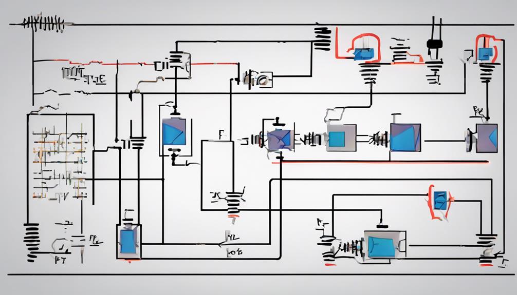
Full-wave rectifiers are crucial when you wish to convert alternating current (AC) into direct current (DC) efficiently. They utilize the entire AC cycle, leading to a higher efficiency of around 81.2% compared to their half-wave counterparts.
Two main types of full-wave rectifiers are commonly used: the center-tapped full-wave rectifier and the bridge rectifier.
In a center-tapped full-wave rectifier, a step-down transformer with a center tap is employed along with two diodes. This setup converts AC to DC by rectifying both halves of the AC waveform into a continuous DC voltage.
On the other hand, a bridge rectifier uses four diodes to achieve the same rectified output without requiring a center tap.
A critical aspect of full wave rectifiers is the ripple factor, which is about 0.48. This factor indicates the amount of AC component present in the DC output. A lower ripple means a smoother DC signal, which is desirable for most applications.
Understanding these components and their configuration helps you ensure the efficient transformation of AC to DC, optimizing the rectified output while minimizing the AC component.
Full Wave Rectifier Circuit Types
When exploring full wave rectifier circuit types, you’ll encounter two main configurations: the center-tapped transformer and the bridge rectifier.
In the center-tapped setup, two diodes work with a step-down transformer to rectify AC into pulsating DC.
On the other hand, the bridge rectifier uses four diodes, offering a more efficient and compact design without needing a center tap.
Center-Tapped Transformer Configuration
In many electronic applications, the center-tapped transformer setup of a full-wave rectifier is essential. Using a step-down transformer and two diodes, this arrangement plays a significant role in power supply circuits. Converting AC to DC leverages the unique center-tapped transformer to achieve higher effectiveness.
Unlike a half-wave rectifier, this configuration fully utilizes both halves of the AC input cycle. The two diodes engage alternately during each cycle, guaranteeing a more consistent DC output. This dual conduction maximizes the energy extracted from the AC source, enhancing the overall efficiency of the conversion process.
The center-tapped full-wave rectifier is especially favored in applications where reliable and efficient power conversion is crucial. The step-down transformer initially reduces the voltage level, making it suitable for subsequent processing. Each diode handles one-half of the AC waveform, working in parallel to smooth out the output.
This results in a more stable DC supply, which is vital for delicate electronic devices. By choosing this configuration, you secure an effective and efficient transformation from AC to DC, making it a cornerstone in many electronic systems.
Bridge Rectifier Design
A bridge rectifier is a highly efficient type of full-wave rectifier circuit that employs four diodes arranged in a bridge configuration. This clever design effectively converts both halves of the AC cycle into DC, making it extremely useful in various power supply circuits.
You’ll find that the bridge rectifier design provides high rectification efficiency and results in a more balanced output compared to other full-wave rectifiers.
One of the standout benefits of a bridge rectifier is its lower ripple factor. This means smoother DC output, which is essential for many electronic devices. Unlike center-tapped configurations, the bridge design doesn’t necessitate a center-tapped transformer, simplifying the circuit and reducing costs.
Using four diodes in the bridge arrangement ensures that the current flows through two diodes at any given time, minimizing power loss and increasing efficiency.
Incorporating a bridge rectifier into your power supply circuit is a wise choice for a compact, efficient design. Its ability to handle higher loads and provide consistent performance makes it a favored choice in modern electronic applications. Embrace this efficient design for your next project!
Diode Arrangement and Function
The arrangement of diodes in a full-wave rectifier is essential for its operation. In a full-wave rectifier circuit, two diodes are strategically placed to allow current flow during each half of the AC cycle, ensuring that the AC input is fully converted into a DC output. This dual diode setup is pivotal, as it utilizes both the positive and negative halves of the AC signal, maintaining a consistent positive voltage for the output.
There are primarily two types of full wave rectifiers: those that use a center-tapped transformer and those that employ a bridge rectifier. Both versions guarantee efficient rectification by harnessing the dual diode configuration.
Here’s a simple comparison:
| Rectifier Type | Diode Count | Configuration Feature |
|---|---|---|
| Center-Tapped | 2 | Uses center-tapped transformer |
| Bridge Rectifier | 4 | No center-tap needed |
| Dual Diode | 2 | Positive and negative half-utilization |
In a bridge rectifier, four diodes form a bridge, allowing for full wave conversion without a center tap, while the dual diode design focuses on maximizing the AC cycle’s output. By understanding these configurations, you’ll see how effectively they convert AC to DC, optimizing the rectifier’s performance.
Operation of Full Wave Rectifiers
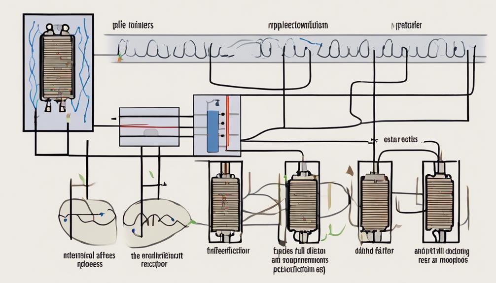
Understanding how diode biasing cycles play an important role is vital when exploring the operation of full-wave rectifiers.
The rectifier converts the entire waveform into a smooth DC output during each AC cycle by switching the diodes’ biasing between positive and negative half cycles.
Additionally, the transformer within the rectifier setup guarantees that the voltage levels are suitable for efficient AC-to-DC conversion.
Diode Biasing Cycles
Understanding the operation of full wave rectifiers starts with grasping the diode biasing cycles. During the positive half cycle of an AC input, full-wave rectifiers use diode biasing to guarantee that one diode is forward-biased while the other is reverse-biased. This arrangement allows the forward-biased diode to conduct current, producing a positive DC output voltage. As the AC waveform shifts into the negative half cycle, the biasing of the diodes switches. The previously non-conducting diode becomes forward-biased, allowing it to conduct and produce a negative voltage output. This alternating biasing cycle is essential for maintaining a continuous pulsating DC output from both half cycles of the AC waveform.
| AC Input Cycle | Diode Biasing Result |
|---|---|
| Positive Half Cycle | Forward bias (Diode 1) |
| Negative Half Cycle | Forward bias (Diode 2) |
| Positive Output | Conducted by Diode 1 |
| Negative Output | Conducted by Diode 2 |
The output current reflects this continuous pulsating DC, as both diodes alternately conduct during their respective cycles. By utilizing both the positive and negative half cycles through efficient diode biasing, full-wave rectifiers effectively convert AC input into a consistent DC output voltage, guaranteeing a stable output current for further use.
AC to DC Conversion
In electronics, converting alternating current (AC) to direct current (DC) is essential, and full-wave rectifiers do this job with impressive efficiency. By utilizing both positive and negative half cycles of AC, full-wave rectifiers convert complete AC cycles into pulsating DC. This method allows them to achieve approximately 81.2% efficiency, outperforming half-wave rectifiers by a large margin.
During each positive half cycle, one diode conducts the voltage while the other blocks it. The roles switch when the cycle turns negative, ensuring a continuous DC output.
The ripple factor, sitting at around 0.48, showcases the smoothness of the DC output. A lower ripple factor means less AC components are mixed in, which is crucial for many electronic devices requiring stable power. Full wave rectifiers are indispensable in power supply units due to their:
- Higher efficiency: They effectively convert more AC into usable DC power.
- Lower ripple factor: They provide a smoother DC output.
- Versatile use: They fit well in various electronic applications.
In short, full-wave rectifiers play an important role in AC-to-DC conversion, ensuring electronic devices receive the stable power they need.
Transformer Role Explained
The essence of a full wave rectifier’s operation lies in the essential role played by the transformer. In full wave rectifiers, the transformer steps down the input AC voltage to a more manageable level, making it suitable for rectification. This step-down process is necessary for converting high-voltage AC to a form that the diodes can handle effectively, guaranteeing efficient conversion of AC to pulsating DC output. By adjusting the voltage levels appropriately, the transformer enables the diodes to work efficiently during both the AC waveform’s positive and negative half cycles.
A step-down transformer guarantees the voltage levels are just right for the diodes’ operation, promoting effective rectification. The full wave rectifier couldn’t perform its job properly without the transformer’s contribution. The transformer’s ability to provide the correct voltage levels is vital for the seamless operation of the rectifier, facilitating the transformation of the entire AC cycle into a usable DC form.
Here’s a quick look at how the transformer impacts the rectification process:
| Function | Role in Rectification | Impact on Output |
|---|---|---|
| Step-Down | Lowers AC Voltage | Makes it manageable |
| Diode Support | Ensures proper operation | Efficient conversion |
| Voltage Control | Stabilizes levels | Positive/Negative Cycles |
Advantages of Full Wave Rectification
Full-wave rectification stands out for its superior effectiveness and performance in converting AC to DC. When you utilize full-wave rectifiers, you’re tapping into a design that maximizes rectification effectiveness, effectively doubling what you’d get from half-wave rectification.
This is because full wave rectifiers harness the entire AC cycle, providing a consistent and higher output current. As a result, the rectified DC output is smoother, with significantly reduced ripple content. This lower ripple factor guarantees that your power supplies maintain a steady and reliable performance, which is essential for numerous applications.
Consider these advantages of full wave rectification:
- Higher Effectiveness: Full wave rectifiers use the entire AC waveform, boosting output voltage and power.
- Smoother DC Output: The rectified DC output is much softer with a lower ripple factor, reducing complex filtering needs.
- Versatile Design: The low ripple content allows simple filters to be integrated, streamlining the rectifier design process.
Incorporating full wave rectifiers into your systems means benefiting from enhanced rectification effectiveness and smoother DC outputs. Whether optimizing power supplies or designing robust circuits, leveraging these rectifiers guarantees stability and improved performance.
Defining Ripple Factor
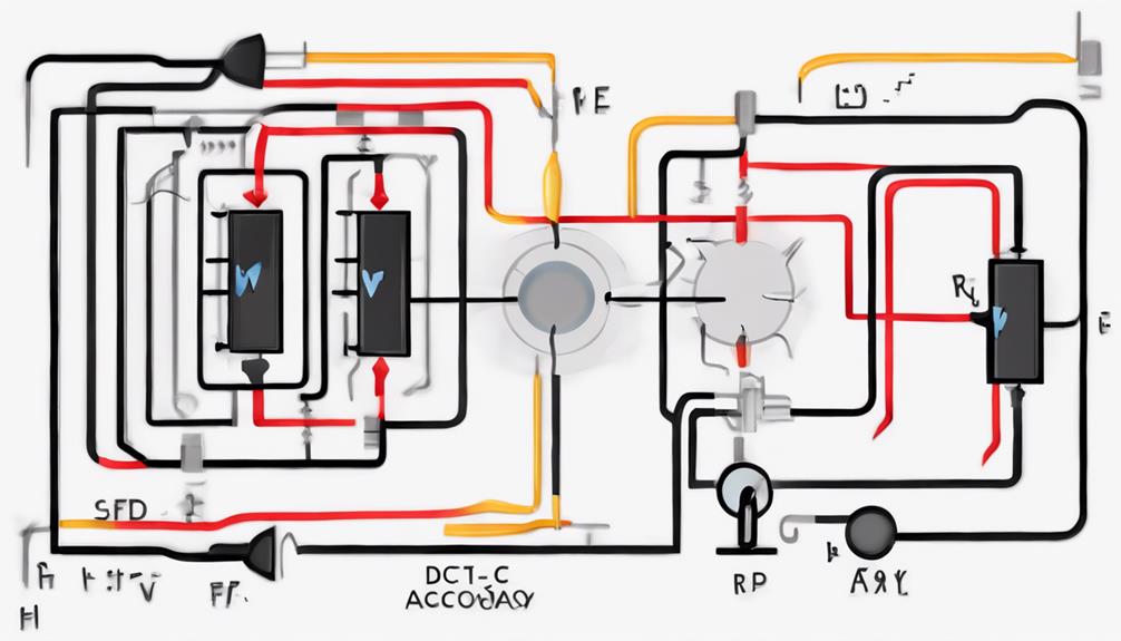
When exploring the concept of the ripple factor, you’ll find it’s an important parameter in the world of rectifiers. The ripple factor is significant because it measures the amount of AC components present in the DC output of a rectified current.
In full wave rectifiers, the ripple factor is approximately 0.48, which highlights the presence of AC ripples that disrupt the smoothness of the DC output.
Understanding the ripple factor can help you assess the quality and efficiency of a full-wave rectifier. A lower ripple factor indicates a more stable and smoother DC output, which is desirable for many applications requiring consistent power delivery.
The ripple factor quantifies how much of the rectified output still fluctuates with AC currents, which can impact the performance of the connected load or circuit.
Recognizing and calculating the ripple factor allows you to effectively design and optimize rectifier circuits. Hence, it’s important to focus on minimizing the ripple factor to enhance the rectifier’s performance and ensure that the DC output is as clean and efficient as possible for your needs.
This understanding is crucial to ensuring that your rectifier circuits operate optimally.
Ripple Factor Formula Explained
Understanding the ripple factor’s significance in rectifiers leads us to its mathematical representation. In the world of Full-Wave Rectifiers, the ripple factor formula is essential for determining the quality of the rectification process. It’s calculated by dividing the RMS value of the AC component present by the average value of rectified DC output. This formula helps quantify the fluctuation in the output voltage or current, providing insight into the efficiency of full-wave rectifiers.
With a ripple factor of approximately 0.48 for Full Wave Rectifiers, you can assess how much AC ripple remains in the otherwise smooth DC output.
A lower ripple factor value is desirable because it signifies:
- A smoother DC output: Less fluctuation in voltage or current.
- Higher efficiency of full wave rectifiers: Better AC to DC conversion.
- Reduced AC component present: A cleaner DC signal.
Importance of Ripple Factor

While delving into electrical engineering, you’ll find that the ripple factor holds the utmost importance in evaluating the efficiency of full wave rectifiers. This metric is essential when converting AC voltage to DC, as it quantifies the amount of fluctuating AC components in the rectifier output. A lower Ripple Factor of Full Wave rectifiers indicates a smoother, more stable DC output, which is vital when designing a power supply unit for electronic devices.
Compared to Half-Wave Rectifiers, the efficiency of half-wave rectifiers is generally lower because they exhibit a higher ripple factor. This means their DC output contains more residual AC, which can lead to instability in power supply units.
On the other hand, full wave rectifiers offer a reduced ripple factor, ensuring a more consistent and reliable DC output.
Understanding and optimizing the ripple factor allows you to better assess your rectifier’s performance. It also aids in designing effective filtering circuits that further smoothen the DC output. This not only enhances the rectifier’s performance but also safeguards electronic devices’ receiving a stable power supply, reducing the risk of damage or malfunction.
Applications and Challenges
Full-wave rectifiers are used in a myriad of applications, from powering televisions to keeping radios running smoothly. Their value lies in their ability to convert AC to DC with a ripple factor of about 0.48. This ripple factor ensures they’re efficient in creating the stable power supplies many electronic devices need. However, the journey from AC to smoothly rectified DC power isn’t without its challenges.
Managing the ripple factor is essential for maintaining lower efficiency loss and a stable power supply. Here’s how it’s typically done:
- Capacitors: These components filter out AC components, smoothing the DC output.
- Optimized Design: Manufacturers aim for designs that naturally minimize ripple.
- Continuous Improvement: There’s an ongoing push to refine materials and methods.
Yet, challenges persist. A ripple factor of 0.48 is generally acceptable but not ideal for sensitive equipment. Devices requiring ultra-stable power might encounter issues, as even small fluctuations can cause performance hiccups. In such cases, additional filtering or advanced regulation techniques become necessary.
Understanding these aspects is vital to maximizing the potential of full-wave rectifiers in varied applications.
Conclusion
To sum up, understanding and optimizing the ripple factor in full wave rectifiers is essential for ensuring stable and reliable DC power output. By reducing the ripple factor, you can enhance the performance and efficiency of your electronic devices and power supply units. This knowledge helps you provide consistent, high-quality power to sensitive equipment, extending its lifespan and improving overall functionality. Monitor and adjust the ripple factor to achieve the best application results.
FAQs
What is the ripple factor in a full-wave rectifier?
The ripple factor measures the residual AC component in a rectifier’s DC output. A full-wave rectifier indicates how effectively the rectifier converts AC to DC, with lower ripple factors meaning smoother DC output. The ripple factor of a full-wave rectifier is generally lower than that of a half-wave rectifier, providing a more stable DC signal.
Key Points:
- Ripple factor measures AC in DC output
- Lower ripple factor = smoother DC output
- The full-wave rectifier has a lower ripple factor than half-wave
How is the ripple factor of a full-wave rectifier calculated?
The ripple factor (γgamma) for a full-wave rectifier is calculated using the formula:
γ=RMS value of AC component C component of the outputgamma = frac{text{RMS value of AC component}}{text{DC component of the output}}
The ripple factor for a full-wave rectifier is approximately 0.48, meaning it produces a relatively low AC component in the DC output.
Key Points:
- Formula: γ=AC component (RMS)DC componentgamma = frac{text{AC component (RMS)}}{text{DC component}}
- Full-wave rectifier ripple factor ≈ 0.48
- Results in low AC ripple for smoother DC
Why is the ripple factor important in rectifiers?
The ripple factor is crucial in rectifiers because it determines the quality of the DC output. A lower ripple factor is desirable in applications that require a stable and smooth DC signal, such as power supplies. With their lower ripple factor, full-wave rectifiers are preferred in these applications due to better DC output quality.
Key Points:
- Lower ripple factor = better DC output quality
- Important for applications needing stable DC
- Full-wave rectifiers offer improved output over half-wave
