

Exploring Full Wave Rectifiers in Modern Circuit Design
Advantages of Full-Wave Rectifiers
The figure below shows the circuit diagram of a Full wave rectifier;

The full-wave rectifier contains diodes D1 & D2, which are connected to the center-tapped secondary coil of a transformer and a load resistance (RL). An AC source is given in the primary coil of the transformer. Notice that only one-half of the total secondary voltage is used for each diode.
Half Wave Rectifier
Operation During Positive and Negative Half-Cycles

During the positive half cycle of the AC input, terminal A is positive concerning B. The diode D1 is forward-biased, allowing current to flow through it, and a voltage is developed across the load resistance RL.
During the negative half cycle, terminal A is negative concerning B. The diode D2 is forward-biased, and current flows through the load resistor RL.
The rectified current flows in the same direction through RL during conduction on either diode. The diodes D1 & D2 conduct alternatively, and both halves of the input appear across the load. Hence, the circuit functions as a full-wave rectifier. The DC output voltage is positive for the common cathodes of the diodes.
During the positive half cycle of the AC input, terminal A is positive concerning B. The diode D1 is forward-biased. The current, therefore, flows through the diode D1, and voltage is developed across the load resistance RL. Solid arrows indicate the direction of the current.
During the negative half cycle, terminal A is negative concerning B. The diode D2 is forward-biased. Consequently, the dotted arrows indicate the current flows through the load resistor RL.
Peak Inverse Voltage
Each diode in a full–wave rectifier is alternatively forward-biased and reverse-biased. When the diode D1 is forward biased, the voltage across the non-conduction diode D2 is equal to the sum of the voltage across the lower half of the secondary coil and the load resistor, i.e., maximum diode voltage VD2 = Vm – (-Vm) =2Vm.
Ripple factor
Efficiency of Rectification
Additional Considerations
Now, let’s explore some additional aspects of full-wave rectifiers:
Merits:
- When compared to a half-wave rectifier, the output voltage is continuous.
Demerits:
- It isn’t easy to locate the center tap on the secondary winding.
- The diode used must have a high PIV.
- The DC output is small as each diode utilizes only one-half of the transformer’s secondary voltage.
- A transformer with a center tap is required.
Applications of Full-Wave Rectifiers
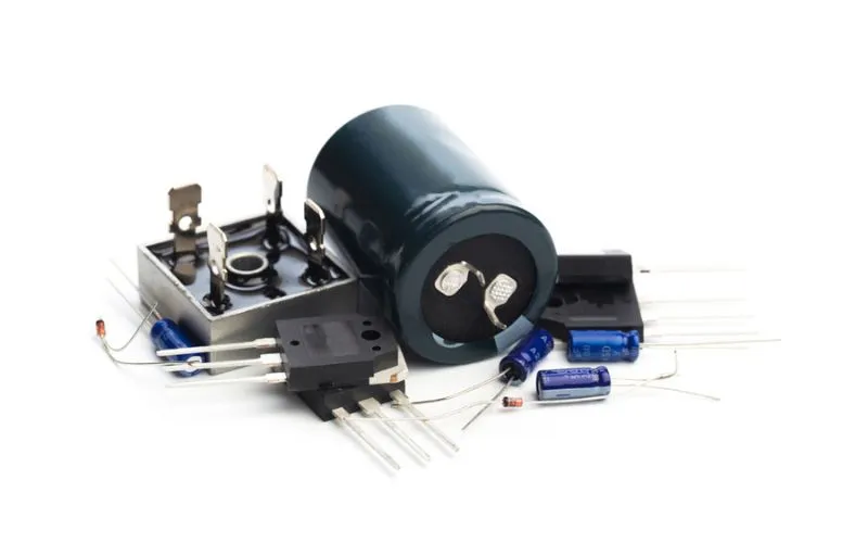
Full-wave rectifiers have extensive use in various applications due to their advantages and efficiency. Some common applications include:
Power Supplies
Full-wave rectifiers are a fundamental component of power supplies in electronic devices. They convert the incoming AC voltage into a stable DC voltage required to power the circuitry.
Battery Charging
Full-wave rectifiers ensure that the battery receives a continuous and regulated DC voltage in battery charging circuits, allowing for efficient charging.
Audio Amplification
Full-wave rectifiers convert AC audio signals into a DC bias voltage needed for proper amplification in audio amplifiers.
Motor Control
In motor control circuits, full-wave rectifiers convert AC voltage into a controlled DC voltage for driving motors and controlling their speed.
Conclusion
Full-wave rectifiers are crucial in efficiently converting AC to DC voltage, making them a fundamental component in various electronic applications. Understanding their operation, characteristics, and applications is essential for anyone working with power electronics. Full-wave rectifiers remain indispensable in modern electronics, whether in power supplies, battery charging, audio amplification, or motor control.
FAQs
1. What is a full-wave rectifier?
A full-wave rectifier is an electronic circuit that converts alternating current (AC) into direct current (DC) by utilizing both halves of the input waveform.
2. What is a full-wave rectifier’s peak inverse voltage (PIV)?
The peak inverse voltage (PIV) is the maximum voltage a non-conducting diode in a full-wave rectifier experiences when reverse-biased. It is equal to twice the peak voltage of the AC input.
3. Where are full-wave rectifiers commonly used?
Full-wave rectifiers find common applications in power supplies, battery charging, audio amplification, and motor control circuits due to their efficiency in converting AC to stable DC voltage.
