

A Comprehensive Guide to Half-Wave Rectifiers in Electronics
What is a Half Wave Rectifier?
A half-wave rectifier is a crucial electronic device that converts AC to DC. Unlike its more complex counterparts, the half-wave rectifier utilizes a single diode to allow only one-half of the AC cycle to pass through, resulting in a pulsating DC waveform.
Half Wave Rectifier Circuit

The circuitry of a half-wave rectifier is elegantly simple. It consists of an AC power source connected in series with a diode and a load resistor. The diode acts as a one-way valve, permitting the flow of current during the positive half-cycle of the AC input and blocking it during the negative half-cycle.
Working of Half Wave Rectifier
Understanding the working of a half-wave rectifier involves dissecting the AC input signal into its positive and negative halves. During the positive half-cycle, the diode conducts, allowing current to flow through and power the load. Conversely, during the negative half-cycle, the diode blocks the current, resulting in a pulsating DC output.
Half Wave Rectifier Capacitor Filter
A capacitor filter can be introduced parallel to the load resistor to mitigate the inherent ripple in the output waveform. This filter smoothens the pulsations in the output, resulting in a more stable DC signal.
Half Wave Rectifier Waveform

The waveform generated by a half-wave rectifier showcases the unidirectional nature of the converted DC signal. The output waveform consists only of the positive half-cycles of the original AC signal, creating a pulsating and somewhat discontinuous DC signal.
Half Wave Rectifier Formula
The efficiency and performance of a half-wave rectifier can be quantified using various formulas. The fundamental formula for the output DC voltage (���) can be expressed as:
���=���
Where �� is the maximum voltage of the AC input.
Ripple Factor of Half Wave Rectifier
The ripple factor (�) is a crucial parameter that quantifies the amount of AC components in the DC output. For a half-wave rectifier, the ripple factor can be calculated using the formula:
�=12
Efficiency of Half Wave Rectifier
The efficiency (�) of a half-wave rectifier is the ratio of DC power delivered to the load to the maximum AC power supplied. The efficiency is given by:
�=1�≈0.3183
RMS value of Half Wave Rectifier
The root mean square (RMS) value of the output voltage (����) is an essential parameter representing the equivalent DC voltage. For a half-wave rectifier, it is calculated as:
����=��2
Peak Inverse Voltage of Half Wave Rectifier
The peak inverse voltage (PIV) is the maximum voltage across the diode in the reverse-bias state. For a half-wave rectifier, the PIV is equal to the peak value of the AC input.
Form Factor of Half Wave Rectifier
The form factor (�) is a dimensionless quantity that characterizes the shape of the output waveform. For a half-wave rectifier, the form factor is given by:
�=�22≈1.11
Output DC Voltage
The output DC voltage is a crucial parameter, representing the average value of the rectified waveform. It is calculated using the formula mentioned earlier.
Advantages of Half Wave Rectifiers
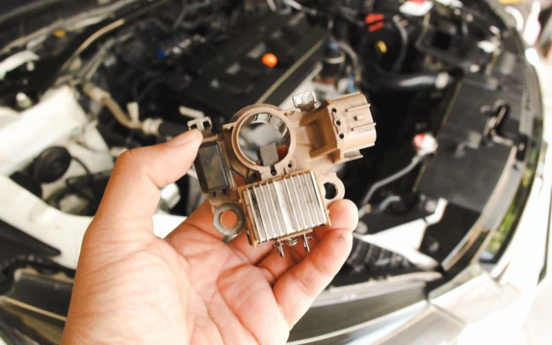
In the world of electronics, simplicity often translates to efficiency. The advantages of half-wave rectifiers lie in their straightforward design and cost-effectiveness.
Simplicity and Cost-Effectiveness
- The minimalistic circuit design leads to cost-effective implementation.
- Suitable for applications where basic rectification suffices.
Educational Value
- It is ideal for educational purposes, aiding in understanding fundamental rectification principles.
- It offers a straightforward platform for students to grasp electronic concepts.
Low Component Count
- Requires fewer components, simplifying maintenance and troubleshooting.
- Well-suited for low-power devices and applications.
Disadvantages of Half Wave Rectifier
While half-wave rectifiers offer simplicity, they come with inherent limitations.
Low Efficiency
- Inefficient compared to full-wave rectifiers due to utilizing only half of the AC cycle.
- Results in a higher percentage of AC components in the output, contributing to lower efficiency.
High Ripple Factor
- The pulsating DC output exhibits a higher ripple factor, impacting the stability of the DC signal.
- Not suitable for applications demanding a smooth and constant DC supply.
Limited Applications
- Not recommended for high-power applications due to its inherent inefficiency.
- Finds its niche in low-power circuits and educational settings.
Applications of Half Wave Rectifier
The versatility of half-wave rectifiers is evident in their applications:
- Battery Charging: Commonly used in simple battery charging circuits for low-power devices.
- Voltage Multipliers: Functions as a crucial building block in voltage multiplier circuits.
- Amplitude Modulation: Applied in amplitude modulation circuits for signal processing.
3 Phase Half Wave Rectifier
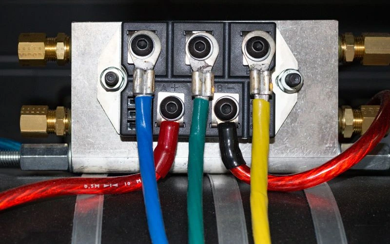
In certain scenarios, three-phase AC power sources may be rectified using a 3-phase half-wave rectifier. This configuration involves using three diodes, each handling one phase, resulting in a more stable DC output than a single-phase half-wave rectifier.
Conclusion
With its simplicity and functionality, the half-wave rectifier is a cornerstone in electronics. From its basic circuitry to the complex mathematical formulations that govern its performance, the half-wave rectifier finds its place in applications ranging from battery charging to signal processing. While its limitations are acknowledged, this device’s educational value and cost-effectiveness continue to make it relevant in various electronic circuits.
Related Article
FAQs
Why is a half-wave rectifier less efficient than a full-wave rectifier?
The half-wave rectifier utilizes only one-half of the AC cycle, resulting in a higher percentage of AC components in the output waveform. This inefficiency contributes to its lower overall efficiency compared to full-wave rectifiers.
Can a half-wave rectifier be used in high-power applications?
Half-wave rectifiers are unsuitable for high-power applications due to their inherent inefficiency and higher ripple factor. They are commonly employed in low-power circuits where basic rectification is sufficient.
How does a capacitor filter improve the output of a half-wave rectifier?
When added in parallel to the load resistor, a capacitor filter smoothens the pulsations in the output waveform, reducing the ripple and providing a more stable DC signal.
