

How to Calculate Leakage Reactance: A Step-by-Step Guide
When you’re looking to calculate leakage reactance in a transformer, initiating a short-circuit test is crucial to assess the total impedance. Once you’ve obtained the test results, you must carefully observe the phase angle between the voltage and current. This angle is crucial for applying the Xl = Zt * sin(phi) formula, where Xl signifies the leakage reactance. But how do you verify your measurements are accurate and that the formula is applied correctly? Let’s delve into the steps and intricacies involved to obtain a dependable value for leakage reactance.
Key Takeaways
- Measure total impedance (Zt) from a short-circuit test, which involves shorting the secondary winding and applying a reduced voltage.
- During the short-circuit test, obtain the phase angle (phi) between current and voltage.
- Calculate the leakage reactance by using the formula Xl = Zt * sin(phi).
- Ensure precise measurements and calculations for accurate leakage reactance determination.
- Validate results by comparing them with reliable sources or seeking expert feedback for confirmation.
Understanding Leakage Reactance

Understanding leakage reactance is crucial for anyone dealing with transformers. It arises from the portion of magnetic flux that doesn’t link the primary and secondary windings, creating a phenomenon known as leakage flux. This leakage flux is essentially the stray magnetic field that only interacts with one set of windings, leading to the self-inductance of each winding.
Leakage reactance is vital in transformers. It contributes to voltage drops and impedance within the windings, impacting the transformer’s overall performance and efficiency.
When calculating leakage reactance, you’ll need to consider geometric factors such as the physical layout of the windings and their proximity to each other. The characteristics of the windings, including their inductance and how tightly they’re wound, also influence the amount of leakage reactance present.
Minimizing leakage reactance can optimize your transformer’s efficiency. By grasping the underlying principles and how leakage flux affects the windings, you can take steps to mitigate its impact. This might involve adjusting the winding configuration or employing specific materials that reduce self-inductance. Accurate calculations and thoughtful design are key to managing leakage reactance effectively.
Conducting a Short-Circuit Test
Conducting a short-circuit test on a transformer is an important procedure to uncover its impedance characteristics. To start, you’ll short the secondary winding of the transformer. Next, a reduced voltage is applied to the primary winding. This setup simulates a short circuit condition and allows you to measure the transformer’s impedance directly.
During this test, you’ll carefully monitor the current flowing through the transformer. You can determine the leakage reactance by analyzing the current, apparent power, and phase angle. The leakage reactance is a vital component of the transformer’s impedance, representing the opposition to the flow of alternating current caused by the transformer’s inductance.
The short-circuit test is invaluable because it provides precise data on the transformer’s impedance components. Understanding these components is important for accurate calculations and efficient transformer design. By conducting this test, you gather essential information that helps calculate the leakage reactance and understand how the transformer will behave under different operating conditions.
Mastering the short-circuit test methodology is important for anyone involved in transformer design or maintenance. It ensures you can accurately determine the leakage reactance, leading to better performance and reliability of the transformer in its intended application.
Measuring Total Impedance

To measure total impedance, start with a short circuit test by applying a reduced voltage to the primary winding and measuring the resultant current. Use this data to calculate the apparent power, which helps you determine the impedance.
Short Circuit Test
The short circuit test is essential for measuring a transformer’s total impedance. This test involves applying a short circuit to the secondary winding of the transformer. This calculates the total impedance, including the transformer windings’ resistance and leakage reactance. Understanding this process is vital for accurately determining the transformer’s impedance and reactance.
During the short circuit test, you must know the current, apparent power, and phase angle. These values allow you to calculate the impedance. The test effectively isolates the leakage reactance by considering the total impedance.
Here’s a simplified breakdown of the process:
| Parameter | How It’s Measured | Purpose |
|---|---|---|
| Current | Measured using ammeter | Needed for impedance calculation |
| Apparent Power | Measured using wattmeter | It helps in determining the total impedance |
| Phase Angle | Measured using a phase angle meter | Critical for accurate calculation |
| Total Impedance | Calculated from current and voltage | Includes resistance and reactance |
Apparent Power Calculation
Calculating the apparent power is vital when measuring the total impedance during a short circuit test. In a 3-phase transformer test, you’re given the current, apparent power, and phase angle. Start by using the phase angle to determine the total impedance. The formula for apparent power (S) is:
[ S = V imes I ]
Where ( V ) is the voltage and ( I ) is the current. But in a short circuit test, the voltage is minimal, so you focus on the current and the phase angle to find the impedance.
The total impedance (Z) can be calculated using:
[ Z = rac{V}{I} ]
However, with the given apparent power and phase angle, you can also use:
[ Z = rac{S}{I^2} ]
Once you have the total impedance, you can separate it into its resistive (R) and reactive (X) components. Leakage reactance (X) is particularly important because it significantly influences transformer performance. Use:
[ X = sqrt{Z^2 – R^2} ]
Understanding this process helps you design and analyze transformer systems effectively. Accurately calculating leakage reactance guarantees the transformer operates efficiently, minimizing losses and enhancing performance.
Determining Magnetizing Reactance
Now, let’s focus on determining magnetizing reactance, which is the inductive impedance from a transformer’s magnetic field.
You’ll need to consider the influence of core material and design, as these factors greatly impact the reactance.
Magnetizing Reactance Principles
Anyone working with transformers must understand the principles of magnetizing reactance. Magnetizing reactance represents the inductive component of the transformer’s impedance due to the magnetizing current required to establish the magnetic field within the core. This concept is vital for determining a transformer’s voltage regulation and efficiency.
Several factors, including the core material, the geometry of the core, and the operating frequency, influence the magnetizing reactance. Fundamentally, the magnetizing reactance is inversely proportional to the core’s permeability and cross-sectional area. This means that:
- Higher permeability: A core with higher permeability will have lower magnetizing reactance.
- Larger cross-sectional area: A larger core area increases the magnetizing reactance.
- Core losses and magnetizing current: These factors need consideration when calculating magnetizing reactance.
To accurately determine magnetizing reactance, you must evaluate the core losses and the magnetizing current necessary to establish the desired magnetic flux path within the core.
This involves understanding how these elements interact within the transformer to affect overall performance. Mastering these principles can enhance the transformer’s design, ensuring efficient functionality and performance.
Core Material Influence
Building on the principles of magnetizing reactance, the choice of core material greatly influences a transformer’s performance. When selecting a core material, you must consider options like silicon steel or amorphous alloys, as these significantly impact the transformer’s performance.
High permeability materials, such as silicon steel, are particularly effective because they reduce the magnetizing current required to establish the magnetic field, thereby enhancing the transformer’s efficiency.
However, it’s not just about reducing the magnetizing current. The losses in the core material also play an important role. Materials with lower core losses, like amorphous alloys, can greatly improve the overall performance of the transformer. These materials minimize energy dissipation, which is crucial for maintaining efficient operation.
Proper core material selection is essential for optimizing the transformer’s magnetizing reactance. High permeability and low-loss materials lead to lower magnetizing reactance, which is advantageous for efficient transformer operation. Choosing the right core material effectively balances permeability and losses, ensuring your transformer operates at its best.
Reactance Calculation Methods
Calculating the magnetizing impedance is crucial in transformer design and performance evaluation. Magnetizing impedance signifies the magnetizing current necessary to establish the magnetic field within a transformer. To determine this, you must divide the open-circuit voltage by the rated current, yielding the magnetizing impedance. This value is vital for understanding the magnetization characteristics and ensuring effective transformer operation.
To calculate the magnetizing impedance accurately, follow these steps:
- Measure the open-circuit voltage: Verify the transformer is unloaded and record the voltage across the primary side. This voltage will mainly account for the magnetizing current.
- Determine the rated current: Identify the rated current for the transformer, usually specified on the nameplate or datasheet.
- Compute the magnetizing impedance: Divide the open-circuit voltage by the rated current. The resulting impedance mainly represents the magnetizing impedance since the resistive component is minimal.
Properly calculating the magnetizing impedance helps evaluate the voltage regulation and overall performance on both the primary and secondary sides. It also aids in optimizing transformer design, ensuring minimal primary leakage and efficient operation. By understanding and applying these methods, you can enhance the reliability and efficiency of your transformers.
Calculating Leakage Reactance
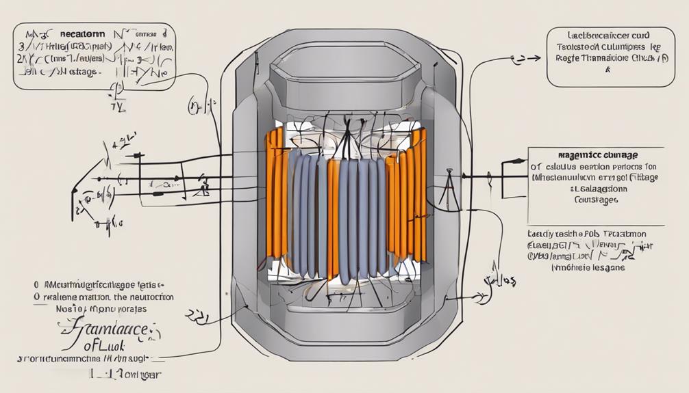
Determining leakage reactance in a transformer depends on the relationship between impedance and the phase angle. To calculate leakage reactance, you’ll use the formula Xl = Zt * sin(phi), where Xl represents leakage reactance, Zt is the total impedance, and phi is the phase angle.
The total impedance is derived from the short circuit test results, which include the measured current, apparent power, and phase angle. First, a short circuit test will be conducted to obtain the necessary values. Measure the current and apparent power under test conditions. Calculate the total impedance, Zt, using the voltage equation ( Zt = rac{V}{I} ), where V is the voltage and I is the current.
Once you have Zt, determine the phase angle and phi from your test data. Next, the formula is applied by multiplying the total impedance by the sine of the phase angle. This step is vital as it directly gives you leakage reactance, significantly impacting voltage regulation and power transfer efficiency in the transformer.
Understanding and accurately calculating leakage reactance ensures that you can design more efficient transformers with minimal power losses, ultimately enhancing performance and stability in your electrical systems.
Validating Your Results
Validating the accuracy of your leakage reactance calculations is fundamental for dependable transformer performance. To confirm your results, compare them with solutions from a manual or other trusted sources. This initial step will help you verify that your primary or secondary winding calculations are on the right path.
Next, consistency is crucial. Carefully review your methods and final answers to ensure they align with established calculation techniques. Small variations might occur due to rounding or different approaches, but significant discrepancies should be investigated.
Understanding each step of the calculation process is also vital. Knowing the reasoning behind each component of your leakage impedance calculations will help you spot errors more easily.
Here are three steps to help validate your leakage reactance results:
- Compare with Reliable Sources: Cross-check your results with a solution manual or credible references.
- Ensure Consistency: Verify that your methods and final answers match known calculation techniques.
- Seek Feedback: Consult with experts or community forums to gain insights and confirm your results.
Conclusion
By following these steps, you’ll accurately calculate the leakage reactance of your transformer. Conduct a short-circuit test, measure the total impedance, and determine the phase angle. Use these values in the Xl = Zt * sin(phi) formula. Ensuring precision at each step helps you get a reliable result. Understanding and calculating leakage reactance is essential for optimizing your transformer’s efficiency and performance. Now, you’re equipped to tackle this vital aspect with confidence.
FAQs
1. What Is the Formula for Leakage Reactance?
For the formula for leakage reactance, you’ll consider inductor design factors and impedance calculations. Include winding turns, core dimensions, and material properties to optimize transformer performance, reduce losses, and improve power transfer efficiency.
2. How to Calculate Leakage Resistance?
To calculate leakage resistance, evaluate the resistivity of materials, winding dimensions, and core properties. Compare leakage resistance sources by analyzing their influence on power losses and efficiency, ensuring you consider the winding design and operating conditions.
3. What Is a Leakage Reactance?
Leakage reactance in transformer design arises from flux that doesn’t fully link primary and secondary windings. Due to the leakage flux path, it represents self-inductance and contributes to electrical losses, affecting voltage drops and overall performance.
4. What Is the Formula for Leakage Inductance?
To find the leakage inductance, use the formula Ll = (N1/Np) 2 * Xl. Mastering this calculation is pivotal, highlighting the significance of leakage reactance in optimizing transformer performance and efficiency.
