

DC Motor Voltage Equation Derivation Explained
When you start exploring the DC motor voltage equation derivation, you’ll need to grasp how applied voltage, back EMF, and armature resistance interplay within the system. Begin by focusing on the basic concepts of DC motors, then move to how these components affect the voltage. By analyzing the armature circle, you’ll see how the generated EMF and armature resistance drop come into play. Neglecting brush drop simplifies the equation to V = Eb + Ia * Ra, but how does this help optimize motor performance? Let’s break it down further.
Key Takeaways
- The DC motor voltage equation is V = Eb + Ia * Ra.
- Applied voltage (V) splits into back EMF (Eb) and armature resistance drop (Ia * Ra).
- Back EMF (Eb) is proportional to motor speed and opposes the applied voltage.
- Armature resistance (Ra) causes a voltage drop when the current (Ia) flows through it.
- The equation helps analyze and optimize motor performance and efficiency.
Basic Concepts of DC Motors
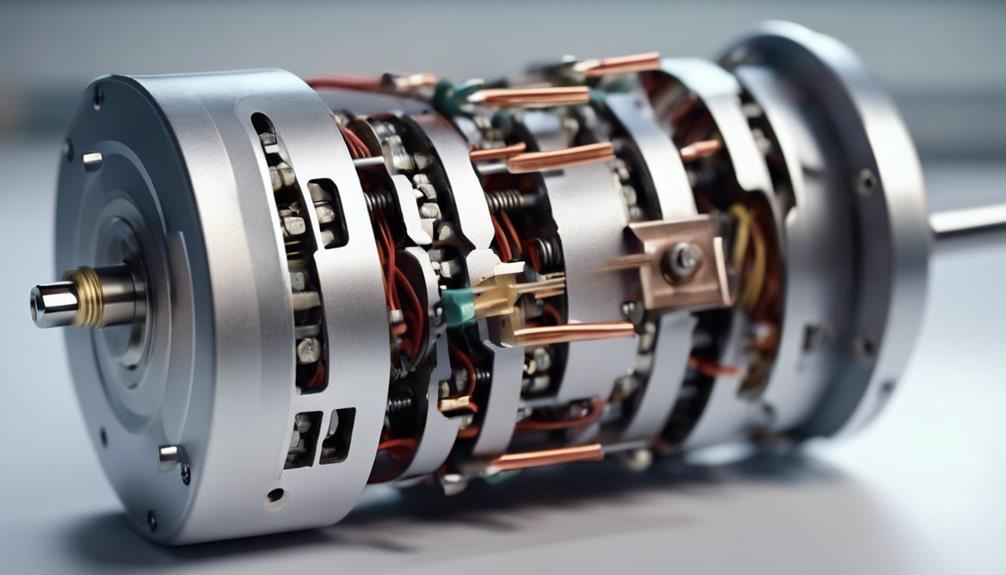
To understand the voltage equation, you first need to grasp the basic concepts of DC motors. A DC motor converts electrical energy into mechanical energy using a simple yet effective principle. The core idea revolves around the relationship between the applied voltage, back EMF, and armature resistance. The DC Motor Voltage Equation is pivotal in this scenario.
When you apply voltage to a DC motor, it drives current through the armature windings. This current generates a magnetic field, causing the armature to rotate. As the armature spins, it produces a counter-electromotive force called back EMF. This back EMF opposes the applied voltage and is directly proportional to motor’sor’s speed.
The DC Motor Voltage Equation can be expressed as:
[ V = E + I cdot R ]
Here, ( V ) represents the applied voltage, ( E ) stands for the back EMF, ( I ) is the armature current, and ( R ) denotes the armature resistance. This equation helps you analyze how electrical input interacts with back EMF to produce mechanical power.
Components Affecting Voltage
Several key components directly affect the voltage in a DC motor, shaping its overall performance and efficiency. First, consider the applied DC voltage, the fundamental driving force for the motor. This applied voltage must overcome the internal resistances and other forces acting within the motor. One critical element here is the armature resistance, which causes a voltage drop proportional to the current flowing through it.
Nethere’sre’s the back EMF (Electromotive Force), a voltage generated by the motor itself as it rotates. The back EMF opposes the applied voltage and is proportional to motor’sor’s speed. This opposing voltage reduces the net voltage across the armature, influencing the current and, ultimately, the motor’s torque and acceleration.
Understanding back EMF is crucial because it directly impacts how efficiently your motor converts electrical energy into mechanical motion.
Armature Circuit Analysis
When you analyze the armature circuyou’llu’ll see how the applied voltage (V) splits between the back EMF (Eb) and the armature resistance drop (IaRa).
Understanding these effects lets you calculate the induced EMF accurately and assess motor’sor’s performance.
This analysis is essential for optimizing efficiency and reducing power losses.
Armature Resistance Effects
Understanding how armature resistance affects yourmotor’sor’s voltage drop is essential for optimizing its efficiency and performance.
When current flows through the armature, the resistance (Ra) in it causes a voltage drop, which can be calculated usOhm’shm’s Law (V = I * Ra). This drop directly impacts the overall voltage available to your motor, reducing its effective operating voltage.
P = I2 * Ra gives the power loss in the armature due to resistance. Higher armature resistance results in increased power loss, primarily in the form of heat, which can further affect the motor’s performance and longevity.
Consequently, if ymotor’sor’s armature resistance is hiyou’llu’ll experience more significant power dissipation, leading to less efficient motor operation.
Induced EMF Calculation
To calculate the induced EMF (Eb) in the armature circuit of your DC motor, you need to analyze the motion of the armature coil within the magnetic field. The induced EMF is generated as the armature coil moves through the magnetic field, opposing the applied voltage—a phenomenon known as back EMF.
The back EMF (Eb) depends primarily on two factors: the motor’s speed and the magnetic field’s strength. To determine the induced EMF, you can use the following equation:
[ E_b = k cdot Phi cdot N cdot omega ]
Where:
- ( E_b ) is the induced EMF.
- ( k ) is a constant.
- ( Phi ) is the magnetic flux.
- ( N ) is the number of turns in the armature coil.
- ( omega ) is the angular velocity of the motHere’sre’s a quick reference table to help understand the parameters:
| Parameter | Symbol | Description |
|---|---|---|
| Induced EMF | ( E_b ) | Voltage generated by the armature motion |
| Magnetic Flux | ( Phi ) | Strength of the magnetic field |
| Turns | ( N ) | Number of turns in the coil |
| Speed | ( omega ) | Angular velocity of the motor |
Understanding induced EMF is essential for deriving the voltage equation of a DC motor and optimizing its performance. By analyzing these factors, you can effectively calculate the back EMF and enhance ymotor’sor’s efficiency.
Generated EMF Calculation
The generated EMF in a DC motor is calculated by taking into account the magnetic flux density, the number of turns in the armature winding, and the speed of rotation. To derive the EMF equatiyou’llu’ll need to understand that the generated EMF (also known as Back EMF) is directly proportional to these factors.
The basic equation for the generated EMF (E) in a DC motor is given by:
[ E = k cdot Phi cdot N cdot omega ]
Here, ( k ) is a constant, ( Phi ) represents the magnetic flux per pole, ( N ) is the number of turns in the armature winding, and ( omega ) is the angular velocity of motor’sor’s armature.
The generated EMF opposes the applied voltage, which is it’sit’s called Back EMF. This opposition reduces the effective voltage across the armature, thereby influencing motor’sor’s speed and performance.
When calculating this Eit’sit’s important to take into account how changes in motor’sor’s speed will impact the Back EMF and, consequently, the overall efficiency and performance of the motor.
Understanding and calculating the generated EMF is essential for analyzing motor’sor’s behavior under various operating conditions, ensuring the best design and operation for your applications.
Armature Resistance Drop
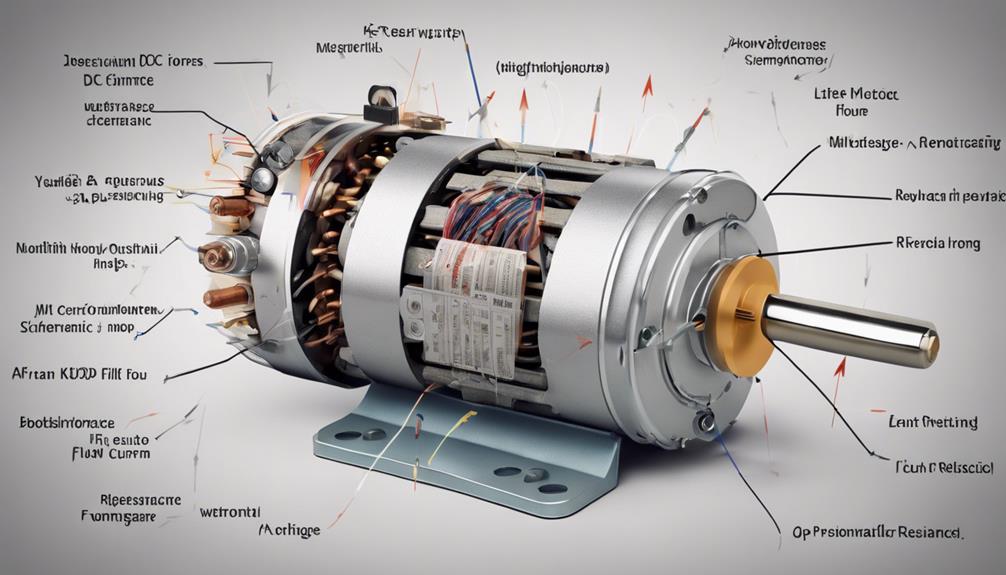
In a DC motor, the armature’s resistance causes a voltage drop that impacts the motor’s overall efficiency and performance. This drop is due to the resistance in the armature circuit and is represented by the term IaRa in the voltage equation. It stands for the armature current, and Ra is the armature resistance.
When the power supply sends current through the motor, this resistance causes a voltage drop across the armature circuit.
The armature resistance drop directly affects motor’sor’s voltage equation. Because of this drop, the voltage available to generate mechanical power is reduced. If the armature resistance is hiyou’llu’ll experience a larger voltage drop, which translates to greater power loss, usually in the form of heat. This not only reduces the efficiency but can also lead to overheating issues.
To improve the efficiency and performance of your DC motit’sit’s important to minimize this resistance drop. Using materials with lower resistance for the armature winding or ensuring proper maintenance can help in reducing this drop.
Back EMF Considerations
When considering back EMF in a DC motyou’llu’ll find it opposes the applied voltage and is essential for motor speed and efficienIt’sIt’s mathematically represented as a function of motor’sor’s speed, directly affecting the effective voltage across the armature.
Understanding back EMF helps you analyze motor characteristics and design effective control strategies.
Definition and Importance
Back EMF, or back electromotive force, is essential for understanding and optimizing DC motor performance. When you explore the DC Motor Voltage Equatiyou’llu’ll find that back EMF is a critical factIt’sIt’s the voltage generated by motor’sor’s armature as it spins in the magnetic field. This generated voltage opposes the applied voltage and is vital in regulating the armature current.
Why is back EMF so important? First, it directly influences motor speed and torque. As the motor speeds up, the back EMF increases, which in turn reduces the net voltage across the armature, thereby limiting the current. This self-regulating feature helps prevent the motor from drawing excessive current and overheating.
Moreover, understanding back EMF considerations in the voltage equation helps you analyze motor efficiency and power consumption. By knowing the back EMF, you can better estimate motor’sor’s performance under various operating conditions, ensuring peak efficiency.
Mathematical Representation
The mathematical representation of the DC motor voltage equation provides a clear understanding of how applied voltage, back EMF, and armature resistance interrelate. At its core, the voltage and EMF equation for a DC motor is expressed as:
[ V = E_b + I_a cdot R_a ]
Here, ( V ) represents the applied voltage, ( E_b ) is the back EMF, ( I_a ) is the armature current, and ( R_a ) is the armature resistance. This equation helps you see how the applied voltage is distributed across motor’sor’s components.
The term ( E_b ) (back EMF) is significant becait’sit’s the voltage generated by motor’sor’s operation, opposing the applied voltage. As the motor speeds up, ( E_b ) increases, reducing the effective voltage across the armature and hence the current ( I_a ). This relationship is essential for understanding motor’sor’s behavior under different operating conditions.
Practical Implications
Understanding how back EMF opposes the applied voltage lets you see how a DC motor naturally regulates its speed and current. When the motor spins, it generates back EMF, which acts against the applied voltage, effectively reducing the voltage across the armature copper. This reduction in effective voltage means less current flows through the armature windings.
Back EMF plays a critical role in limiting the armature current. Without it, the current would only be governed by the resistance of the armature copper, which is typically very low, leading to excessive current and power consumption. By opposing the applied voltage, back EMF ensures that the motor draws only the necessary current based on its speed, resulting in efficient operation.
The difference between the applied voltage and back EMF determines the armature current flow. As the motor speeds up, back EMF increases, reducing the effective voltage and therefore the armature current. Conversely, if the motor slows down, back EMF decreases, allowing more current to flow and providing the necessary torque to accelerate back to the desired speed.
Neglecting Brush Drop

Neglecting the brush drop simplifies the voltage equation for a DC motor, making it easier to analyze key components like back EMF and armature resistance. You can focus on the more significant factors that influence motor performance by omitting the brush drop, which is often negligible compared to other voltage drops in the system. This simplification helps you zero in on the core elements of the equation of DC motor operation without getting bogged down by minor details.
When you disregard the brush drop, the voltage equation primarily revolves around two main components: the back EMF and the voltage drop across the armature resistance. The back EMF (Electromotive Force) is generated by motor’sor’s rotation and opposes the applied voltage, while the armature resistance represents the inherent resistance within motor’sor’s windings. By concentrating on these factors, you can more accurately derive and understand the equation of DC motor voltage.
This approach not only streamlines the derivation process but also provides a clearer picture of themotor’sor’s electrical behavior. Understanding this simplified model is essential for accurate performance analysis and effective troubleshooting.
General Voltage Equation
To understand the general voltage equation of a DC motyou’llu’ll need to break down the armature voltage components and the back EMF derivation.
This equation balances the applied voltage with the back EMF and the voltage drop across the armature resistance.
Armature Voltage Components
The general voltage equation for a DC motor breaks down the applied voltage into components like back EMF, armature resistance drop, and terminal voltage. Wyou’reu’re dealing with a DC motor, understanding this voltage equation is important. It helps you see how the applied voltage is split between the back EMF and the armature resistance. Essentially, the applied voltage (V) can be expressed as the sum of the back EMF (E_b) and the voltage drop across the armature resistance (I_a * R_a).
In simple terms, V = E_b + I_a * R_a. Here, V is the terminal voltage, E_b is the back EMF, I_a is the armature current, and R_a is the armature resistance. This equation is your key to analyzing the performance and efficiency of your DC motor. By knowing the values of the armature resistance and the current, you can calculate the back EMF and understand how much voltage is being used to overcome motor’sor’s internal resistance.
This breakdown is essential for predicting motor behavior under different load conditions. It helps you troubleshoot issues, optimize performance, and make sure your DC motor operates efficiently and reliably.
Back EMF DerivatLet’set’s break down how back EMF is derived in the general voltage equation for a DC motor. When the armature coil of a DC motor rotates within a magnetic field, it generates a voltage called back EMF (Eb).
This back EMF is important because it opposes the applied voltage (V), thereby playing a significant role in regulating motor’sor’s armature current and preventing excessive power consumption. Back EMF is directly proportional to motor’sor’s speed. As the speed increases, the back EMF rises, which limits the current flowing through the motor.
Mathematically, back EMF can be expressed as Eb = kΦω, where k is a constant, Φ is the magnetic flux, and ω is the angular velocity.
Incorporating back EMF into the voltage equation, you get the general voltage equation for a DC motor: V = Eb + IaRa. Here, V is the applied voltage, Ia is the armature current, and Ra is the armature resistance.
This equation helps you analyze the DC motor’s overall performance and efficiency. Understanding how to derive and utilize back EMF in the voltage equation is essential for designing and optimizing DC motor systems effectively.
Practical Applications
Understanding the DC motor voltage equation empowers you to design more efficient electrical systems, optimize motor performance, and enhance power efficiency. The power equation of a DC motor plays an essential role in this process. By mastering this equation, you can predict how changes in voltage, back EMF, and armature resistance affect overall motor performance. This knowledge is critical for a wide array of practical applications.
For instance, in motor control, you can precisely regulate speed and torque. Analyzing the voltage equation lets you understand how to apply just the right voltage to achieve desired performance levels. This is particularly important in robotics, electric vehicles, and industrial automation, where precise control is crucial.
Moreover, the voltage equation helps in speed regulation. Adjusting the input voltage and accounting for back EMF allows you to maintain consistent motor speed under varying loads. This is important in conveyor systems and other machinery that require stable operation.
Lastly, considering power efficiency, the voltage equation helps minimize energy losses. By optimizing the electrical input parameters, you can ensure that your DC motor operates at peak efficiency, conserving energy and reducing operational costs.
Performance Characteristics
Leveraging the principles outlined in the voltage equation, you can gain deep insights into a DC motor’s performance characteristics.
The voltage equation, ( V = E_b + I_a R_a ), where ( V ) is the applied voltage, ( E_b ) is the back EMF, ( I_a ) is the armature current, and ( R_a ) is the armature resistance, governs the distribution of electrical power within the motor.
Understanding this equation allows you to analyze how the motor operates under different conditions. For instance, back EMF, which opposes the applied voltage, increases with motor’sor’s speed. When the motor runs faster, back EMF rises, reducing the armature current and torque.
Conversely, when the motor slows down, back EMF decreases, increasing the armature current and torque. Armature resistance also plays an important role. High armature resistance causes more voltage to drop across the armature, leading to higher power losses and reduced efficiency.
Conclusion
To sum up, by grasping how applied voltage, back EMF, and armature resistance interayou’veu’ve learned to derive the DC Motor Voltage Equation: V = Eb + Ia * Ra.
This fundamental equation helps you predict and optimize motor performance by analyzing electrical power distribution.
With this knowledyou’reu’re equipped to tackle various operating conditions and enhance the efficiency of DC motor systems in practical applications.
FAQs
What is the voltage equation for a DC motor?
The voltage equation for a DC motor relates the input voltage to the electrical and mechanical parameters of the motor. The basic voltage equation for a DC motor is:
V=Eb+IaRaV = E_b + I_a R_a
Where:
- VV is the applied voltage to the armature (in volts).
- EbE_b is the back electromotive force (back EMF) generated by the motor (in volts).
- IaI_a is the armature current (in amperes).
- RaR_a is the armature resistance (in ohms).
How is the DC motor voltage equation derived?
The derivation of the DC motor voltage equation involves understanding the principles of electromagnetism and circuit analysis within the motHere’sre’s a step-by-step explanation:
- Armature Circuit:
- Concept: A DC motor’s DC motor’s armature can be modeled as a series circuit containing the armature resistance (RaR_a) and the back EMF (EbE_b). The input voltage (VV) is applied across this series circuit.
- Kirchhoff’s Voltage Law (KVL):
- Application: AccordingKirchhoff’sff’s Voltage Law, the sum of the voltage drops around a closed loop is equal to the applied voltage. For the armature circuit: V=IaRa+EbV = I_a R_a + E_b
- Here, IaRaI_a R_a is the voltage drop across the armature resistance, and EbE_b is the back EMF generated by the motor.
- Back EMF (EbE_b) Expression:
- Concept: Back EMF (EbE_b) is the voltage induced in the armature windings due to motor’sor’s rotation. It can be expressed as: Eb=keΦNE_b = k_e Phi N
- Where:
- kek_e is a constant depending on the construction of the motor.
- ΦPhi is the magnetic flux per pole (in webers).
- NN is the speed of the motor in revolutions per minute (RPM).
- Substituting Back EMF into the Voltage Equation:
- Step: Substitute the expression for EbE_b into the KVL equation: V=IaRa+keΦNV = I_a R_a + k_e Phi N
- This equation shows how the applied voltage VV is related to the armature current IaI_a, the armature resistance RaR_a, and the back EMF EbE_b (which depends on the motor speed and magnetic flux).
- Simplification:
- Simplification: Depending on the specific motor, the constant kek_e and magnetic flux ΦPhi might be combined into a single constant for simplification. However, the key idea remains that the input voltage is the sum of the voltage drop across the armature resistance and the back EMF.
What does the DC motor voltage equation tell us?
The DC motor voltage equation provides important insights into motor’sor’s operation:
- Relationship Between Voltage, Current, and Speed:
- Insight: The equation shows that the applied voltage overcomes the armature resistance and generates the back EMF, which is proportional to the motor’s speed. This explains why, as the speed increases, the back EMF increases, reducing the motor’s current draw.
- Speed Control:
- Insight: By controlling the applied voltage VV, you can control the motor speed NN. Increasing the voltage increases the speed, while decreasing the voltage reduces the speed.
- Motor Performance:
- Insight: The equation is crucial for designing and analyzing the performance of DC motors, allowing engineers to predict how changes in voltage, resistance, or flux will affect motor’sor’s operation.
