

Open Circuit and Short Circuit Tests of Transformer: Explained
When you are a transfotransformer’smance, understanding the Open Circuit and Short Circuit tests is essential. These tests, which measure core losses, no-load current, full-load current, and copper losses, offer an all-encompassing view of how the transformer operates under different conditions. You can pinpoint key parameters like efficiency and voltage regulation by interpreting the data from these procedures. But how exactly do these tests work, and what steps should you follow to conduct them accurately? The nuances of these tests reveal much about a transfotransformer’sor and reliability.
Key Takeaways
- Open circuit tests measure no-load current and core losses by energizing the primary winding with the secondary winding open.
- Short circuit tests measure copper losses and full-load current by shorting the secondary winding and gradually increasing the primary voltage.
- Core losses are determined during the open circuit test through power consumption measurements with the secondary winding open.
- Copper losses are determined during the short circuit test using a wattmeter, ammeter, and voltmeter readings.
- Test results provide equivalent circuit parameters, efficiency, and voltage regulation insights.
Transformer Testing Fundamentals
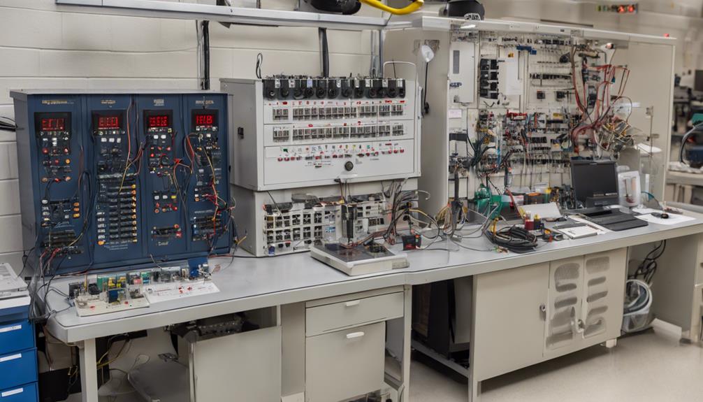
Understanding transformer testing fundamentals is vital for anyone involved in electrical engineering. By conducting open circuit and short circuit tests, you can gather critical data on a transformer’s performance without fully loading it. These tests help determine key parameters such as turns ratio, regulation, and efficiency, which are pivotal for evaluating and optimizing transformer operations.
In an open circuit test, you apply a voltage to one winding while the other remains open, allowing you to measure no-load current and core losses. This gives insight into the transfotransformer’sic circuit and helps identify constant core losses.
On the other hand, a short circuit test involves applying a reduced voltage to one winding while the other is short-circuited. It focuses on measuring full-load current and copper losses, which vary with current.
Analyzing the results from these tests allows you to determine the equivalent circuit parameters of the transformer. This includes understanding the power losses in both the core and the coils, which is vital for calculating efficiency.
Open Circuit Test Process
Performing an open circuit test on a transformer is a straightforward yet pivotal procedure for evaluating its core characteristics. First, you’ll open the secondary winding while energizing the primary side at the rated voltage. This setup allows you to measure the primary voltage, current, and power to determine core losses and exciting current under no-load conditions.
Here’s A rundown of the steps involved:
- Energize the primary winding: Open the rated voltage to the primary winding with the secondary circuit.</li>
- Measure primary voltage: Use a voltmeter to confirm the applied voltage is at the rated level.
- Measure primary current: Record the no-load current using an ammeter.
- Measure input power: Use a wattmeter to measure consumed power, mainly representing core losses.
- Calculate equivalent circuit parameters: Analyze these measurements to derive the core loss and exciting current necessary for evaluating transformer efficiency and voltage regulation.
The primary objective is to gauge the transfotransformer’s competency, voltage regulation, and core characteristics. By examining the results, you can assess performance and make necessary adjustments.
This Open Circuit Test complements the Short Circuit Test, forming the backbone of transformer tests to ensure ideal operation.
Short Circuit Test Procedure
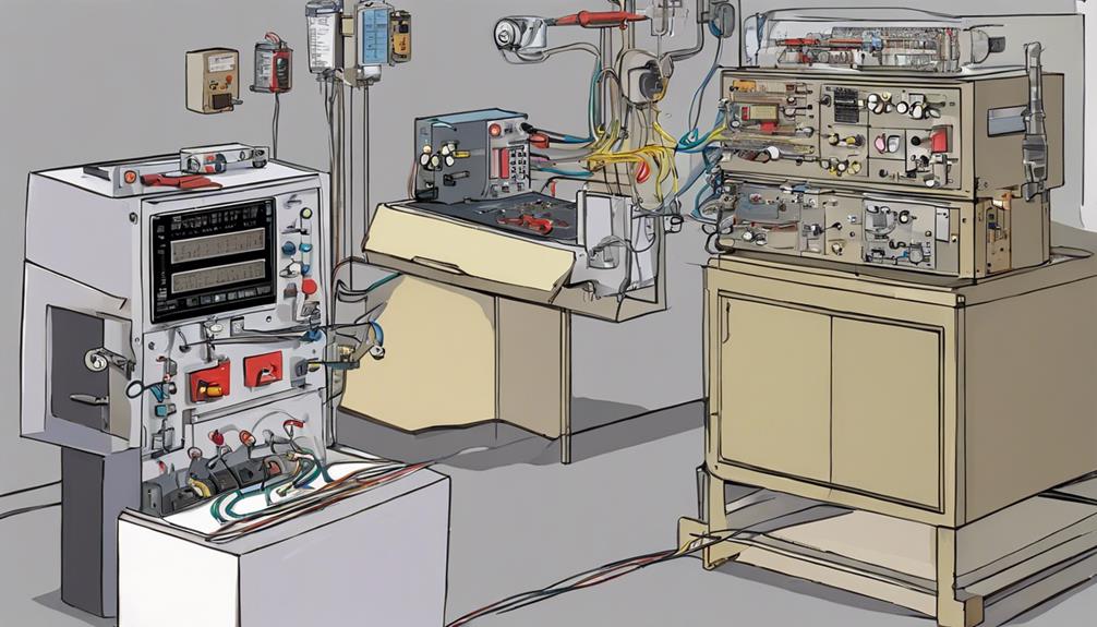
During the short circuit test, you’ll use the ary winding and apply a low voltage to the primary side to accurately evaluate copper losses and impedance. This setup allows you to determine how the transformer performs under full load conditions without applying high voltage, which could be risky.
First, connect a wattmeter, ammeter, and voltmeter to the primary winding—short the secondary winding using a thick conductor to guarantee minimal resistance. Gradually increase the voltage on the primary side until the primary current reaches its full load value. The wattmeter readings will primarily indicate the copper losses in the transformer. These readings are crucial for determining the parameters needed to estimate the transfotransformer’slent.
Here’s Here’sary of the steps involved:
| Step | Action | Purpose |
|---|---|---|
| 1 | Connect meters to the primary winding | Measure voltage/current |
| 2 | Short secondary winding | Ensure minimal resistance |
| 3 | Gradually increase primary voltage | Achieve full load conditions |
| 4 | Record wattmeter, ammeter, and voltmeter readings | Determine copper losses |
Analyzing Test Results
Evaluating the results of both open-circuit and short-circuit tests gives you a thorough understanding of your transfotransformer’smance metrics. These analyses help you determine core losses, copper losses, and equivalent circuit parameters, which are critical for predicting transformer efficiency and voltage regulation.
By accurately calculating core and copper losses, you can optimize transformer design and ensure effective transformer operation. The parameters obtained from these tests provide insights into the behavior and characteristics of transformers under different load conditions. Properly interpreting these test results is essential for guaranteeing safe, reliable, and effective transformer operation.
Here are the key aspects to focus on during the test results analysis:
- Core losses: These are determined from the open-circuit test and indicate the energy lost in the transfotransformer’s shopper losses. These are derived from the short-circuit test and represent the energy lost in the windings due to resistance.
- Equivalent circuit parameters: These values help model the transformer for further analysis.
- Transformer efficiency: Understanding losses helps calculate the efficiency of the transformer.
- Voltage regulation indicates how well the transformer maintains constant voltage under varying load conditions.
Practical Applications

You can apply these findings to real-world scenarios with a solid grasp of analyzing test results. Open and short circuit tests are essential for determining vital parameters in transformer design and efficiency. Using these tests, you can predict transformer behavior under different load conditions, which is fundamental for optimizing performance and ensuring reliable operation.
When you perform an open circuit test, you measure the core loss by connecting the primary side to the power supply and leaving the secondary side open. Using a wattmeter and ammeter, you can determine the core loss accurately. This test helps you understand how the transformer will perform under no-load conditions.
On the other hand, the short circuit test involves connecting the secondary side short and applying a reduced voltage to the primary side. This allows you to measure copper losses and equivalent impedance. The results from these tests give you valuable insights into the transfotransformer’s competency and regulation.
Conclusion
You gain critical insights into its performance by conducting the Open Circuit and Short Circuit tests on a transformer. These tests let you determine core losses, no-load current, full-load current, and copper losses. With this data, you can calculate efficiency, regulation, and equivalent circuit parameters. Ultimately, these tests help the transformer operate efficiently under various conditions, guiding you in making informed maintenance and operational effectiveness decisions.
FAQs
What is the open circuit test of a transformer?
The open circuit test of a transformer is performed to determine the transfotransformer’sosses (hysteresis and eddy current losses) and to measure the no-load current. In this test, the secondary winding is left open, and the test is conducted on the primary side of the transformer by applying the rated voltage.
Key Points:
- Conducted with the secondary winding open.
- Measures core losses (no-load losses).
- Determines no-load current and power factor.
How is the open circuit test conducted?
To perform the open circuit test:
- Open the Secondary Winding: The secondary winding is left open, meaning no load is connected.
- Apply Rated Voltage: A voltage is applied to the primary winding (usually at the rated voltage), and instruments measure the primary voltage, current, and power.
- Measure Core Losses: The power measured in this test corresponds to the core losses in the transformer, as the copper losses are negligible due to the small no-load current.
- Calculate Parameters: Based on the readings, you can calculate the no-load power factor, core losses, and magnetizing current.
Steps:
- Secondary winding left open.
- Apply rated voltage to the primary winding.
- Measure voltage, current, and power to calculate core losses.
What is the short circuit test of a transformer?
The short circuit test measures the copper losses (I²R losses) and determines the transformer’s equivalent impedance and voltage regulation. In this test, the secondary winding is shorted, and a reduced voltage is applied to the primary winding.
Key Points:
- Conducted with the secondary winding shorted.
- Measures copper losses under full load conditions.
- Determines equivalent impedance and voltage regulation.
How is the short circuit test conducted?
To perform the short circuit test:</p>
- Short the Secondary Winding: The secondary winding of the transformer is shorted using a thick wire.
- Apply Reduced Voltage: A small voltage, typically much lower than the rated voltage, is applied to the primary winding until the rated current flows through the windings.
- Measure Copper Losses: The power measured in this test corresponds to the copper losses in the transformer, as the core losses are negligible due to the low applied voltage.
- Calculate Parameters: From the measurements, you can calculate the transfotransformer’slent impedance and its copper losses under full load conditions.
Steps:
- Short the secondary winding.
- Apply reduced voltage to the primary until the rated current flows.
- Measure voltage, current, and power to calculate copper losses.
What are the objectives of the open circuit and short circuit tests?</h4>
The main objectives of conducting open circuit and short circuit tests are to:
- Determine Efficiency: These tests help calculate the efficiency of the transformer by determining the core and copper losses.
- Measure Losses: Open circuit tests measure core losses, while short circuit tests measure copper losses under full load.
- Evaluate Voltage Regulation: The short circuit test helps assess the transfotransformer’se regulation by measuring the voltage drop across the windings.
- Avoid Full Load Testing: These tests allow the transfotransformer’s performance to be evaluated without applying a full load, reducing risk and costs.
Key Objectives:
- Determine transformer efficiency.
- Measure core and copper losses.
- Evaluate voltage regulation.
- Avoid full-load testing.
Why are open circuit and short circuit tests important for transformers?
These tests are important because they:
- Assess Performance: They allow engineers to assess a transformer’s performance and efficiency without applying full load conditions.
- Determine Losses: Understanding core and copper losses helps optimize the transfotransformer’s operation and improve energy efficiency.
- Ensure Safe Operation: Conducting these tests ensures that transformers can operate safely under both no-load and load conditions, helping prevent overheating or malfunction.
Importance:
- Help in assessing transformer performance.
- Measure essential parameters like losses and impedance.
- Ensure transformers operate safely under various conditions.
