

Wien Bridge Oscillators: Design, Working & Applications
Imagine you’re stepping into the world of electronic circuits where precision meets simplicity. The Wien Bridge Oscillator stands out as a classic design that generates pure sine waves with ease. With its unique arrangement of resistors and capacitors, it promises stable frequencies and reliable performance. But what makes it tick, and how does it maintain those perfect waves? Let’s uncover the secrets behind its enduring allure and practical applications.
Key Takeaways
- The Wien Bridge Oscillator generates precise sine waves using a bridge circuit and is essential for creating stable oscillations.
- It requires a voltage gain of at least three and zero phase shift at the resonant frequency for sustained oscillations.
- The oscillator uses a band-pass filter to allow specific frequencies to pass while attenuating others.
- Amplitude stabilization is achieved using filament lamps, diodes, or thermistors to maintain consistent output levels.
- Modern designs can achieve distortion levels as low as 0.0003%, which is essential for high-precision applications.
Historical Development and Key Innovations
During the 1930s, the Wien Bridge Oscillator underwent considerable advancements, largely due to Frederick Terman’s emphasis on automatic amplitude control in oscillators. You can trace its historical development to Terman’s pioneering work, which underscored the need for amplitude stabilization.
In 1937, Larned Meacham’s patent marked a key innovation by utilizing filament lamps for gain control, significantly enhancing oscillator design.
Bill Hewlett’s introduction of the HP200A in 1939 further cemented the Wien Bridge Oscillator’s commercial viability. His work, along with that of Terman and Meacham, highlighted critical feedback techniques that shaped modern oscillators.
These key innovations in automatic amplitude control laid the groundwork for future designs, ensuring the Wien Bridge Oscillator remained pivotal in the technological evolution.
Overview and Characteristics of Wien Bridge Oscillator
You’ll find the Wien Bridge Oscillator fascinating as it generates precise sine waves across various frequencies using a bridge circuit.
To calculate the frequency of oscillation, use the formula (_{Hz} = frac{1}{2pi R}), which takes into account the resistance and capacitance in the setup.
The phase shift ranges from 90° leading to 90° lagging, with stable oscillation achieved at zero phase shift, showcasing its unique phase shift characteristics.
Sine Wave Generation
The Wien Bridge Oscillator is a widely used circuit for generating stable sine waves over a broad frequency range. It achieves sine wave generation through a precise oscillation frequency determined by the resistor and capacitor values in the circuit.
This setup ensures stable oscillations with minimal distortion, making it ideal for audio frequency applications. By maintaining a zero phase shift at the resonant frequency, the oscillator produces continuous oscillation without needing an external signal.
Positive feedback is essential in this process, guaranteeing good stability and consistent performance. The circuit’s design, featuring a combination of resistors and capacitors, enables it to adapt across varying frequencies, with phase shifts ranging from 90° leading to 90° lagging, optimizing for stable and precise sine wave outputs.
Frequency Calculation Formula
Understanding sine wave generation in the Wien Bridge Oscillator naturally leads to examining its frequency calculation formula. You calculate the frequency of oscillation using ( f_{Hz} = frac{1}{2pi RC} ), where the resistors and capacitors in the RC network determine the frequency.
This precise formula helps guarantee the oscillator maintains stability and consistent amplitude in its output. The circuit’s performance is highly sensitive to component values, making careful selection of these components crucial.
Here’s what you need to know:
- Frequency: Determined by the RC network.
- Oscillation: Achieved with zero-degree phase shift.
- Stability: Enhanced by balanced resistor-capacitor ratios.
- Output: Affects the amplitude and frequency range.
- Component values: Key to achieving the desired oscillation.
Adjusting these elements helps maintain effective feedback and oscillation.
Phase Shift Characteristics
How exactly does the Wien Bridge Oscillator manage phase shift to produce stable oscillations? It achieves this through a delicate balance of resistor and capacitor values within its feedback network. At the oscillation frequency, the phase shift is zero, meaning the input and output signals are in phase, which is vital for frequency stability. The gain of the amplifier is set to maintain this condition, guaranteeing a consistent sinusoidal output. Wien bridge oscillators shift from 90° leading at low frequencies to 90° lagging at high frequencies. Understanding these phase shift characteristics is essential for anyone designing circuits that require precise oscillation control.
| Frequency Range | Phase Shift |
|---|---|
| Low | 90° Leading |
| Resonant | 0° (In-phase) |
| High | 90° Lagging |
This balance guarantees reliable operation and stable oscillations.
RC Network Configuration and Functionality
When examining the RC network configuration in a Wien Bridge Oscillator, you’ll find that the band-pass filter is central to its operation, allowing specific frequencies to pass while attenuating others.
Each RC network acts as a voltage divider, where the arrangement of resistors and capacitors determines the resonant frequency.
Band-Pass Filter Design
Though the Wien Bridge Oscillator is a versatile circuit, its heart lies in the band-pass filter design of its RC network configuration.
You’ll find that it uses two RC networks to pass a specific frequency, while attenuating other frequencies selectively. This design is crucial for maintaining precise oscillation frequency and amplitude stability.
Here’s how it works:
- The Wien Bridge forms a band-pass filter using a series RC network (Z1) and a parallel RC network (Z2).
- Impedance balance occurs when the ratios of resistance and capacitance equalize.
- The voltage divider takes its output from the junctions of Z1 and Z2.
- Component values, such as R1, R2, C1, and C2, determine the resonant frequency.
- A proper balance ensures a stable feedback path, resulting in a consistent output signal.
Voltage Divider Network
Building on the band-pass filter design, the voltage divider network in the Wien Bridge Oscillator is pivotal for its RC network configuration and functionality.
It employs two RC circuits: a series impedance (Z1) comprising a resistor (R1) and a capacitor (C1), and a parallel impedance (Z2) consisting of a resistor (R2) and a capacitor (C2). This setup creates a band-pass filter that outputs one-third of the input voltage (Vin) at the resonant frequency, ensuring smooth oscillation.
The Wien bridge oscillator cleverly balances feedback signals by splitting them between the amplifier’s inverting and non-inverting inputs. This facilitates both positive and negative feedback, maintaining consistent oscillation.
For example, using R1 = R2 = 12kΩ and C1 = C2 = 3.9nF tunes it to 3.4kHz.
Gain, Phase Shift, and Conditions for Oscillation
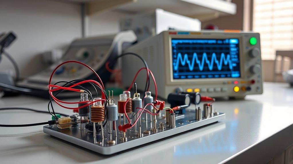
To guarantee a Wien bridge oscillator functions at its best, it’s vital to understand the relationship between gain, phase shift, and the conditions necessary for oscillation. Achieving a voltage gain of at least three is essential for sustained oscillation, as it confirms the output regenerates effectively.
At the resonant frequency, the phase shift hits 0°, maximizing feedback for continuous oscillation. Here’s what you need to know:
- Gain: Must be at least 3 for constant oscillation.
- Phase Shift: At the resonant frequency, it’s 0°, resulting in maximum feedback.
- Oscillation Frequency: Calculated using (f = frac{1}{2pi RC}).
- Component Ratios: Equal resistor and capacitor ratios guarantee stability.
- Frequency Shift: Positive at low and negative at high frequencies.
Understanding these elements helps balance and maintain oscillation stability.
Amplitude Stabilization Techniques
When it comes to amplitude stabilization in Wien bridge oscillators, maintaining a consistent output level is key to preventing signal clipping and ensuring continuous oscillation.
You’ll find that filament lamps, introduced by Larned Meacham in 1938, employ temperature-dependent resistance to achieve this. As the oscillation level rises, the filament’s resistance increases, providing negative feedback that stabilizes the output amplitude. Incandescent bulbs were once a popular choice for this method.
However, modern designs have improved on this by using diodes, thermistors, or FETs. These components offer more precise control, resulting in lower distortion levels and enhanced performance.
Achieving low distortion is essential, with contemporary circuits reaching impressively low distortion levels of just 0.0003% (3ppm).
Technical Performance and Limitations
As you’ve seen with amplitude stabilization in Wien bridge oscillators, achieving consistent output is just one part of the equation.
The Wien bridge oscillator excels in frequency stability, especially at low frequencies, ensuring reliable circuit performance for precision applications.
However, certain limitations need consideration:
- Inductive nature: Coiled filaments in light bulbs can hinder high-frequency response.
- Design challenges: The current requirements of incandescent bulbs often exceed the capabilities of standard operational amplifiers.
- Low distortion: Modern components achieve distortion levels as low as 0.0003%, enhancing performance.
- Temperature sensitivity: Similar to commercial receivers, fewer adjustments mean reduced sensitivity.
- Amplitude stabilization: While beneficial, it demands careful component selection.
Applications and Modern Implications
The Wien bridge oscillator remains a cornerstone in modern electronics, offering versatile applications across various fields. As an audio frequency oscillator, it generates stable sine waves with low distortion, making it perfect for sound synthesis and testing audio equipment.
You’ll appreciate its automatic gain control, which adapts seamlessly to varying circuit conditions for reliable, real-time signal processing. Historically, it played an essential role in developing feedback techniques, influencing current electronic design and signal generation.
In modern contexts, the oscillator plays a critical role in precise frequency measurement, modulation-demodulation circuits, and numerous scientific research applications. SPICE simulations and online tools make experimenting with the Wien bridge oscillator accessible, enhancing both educational and practical learning for engineers and students alike.
Conclusion
You’ve explored the fascinating world of the Wien Bridge Oscillator, a pivotal tool in generating precise sine waves. By mastering its RC network and ensuring zero phase shift, you can achieve stable oscillations. With amplitude stabilization techniques like filament lamps and diodes, this oscillator remains a staple in signal processing and audio applications. Despite its limitations, the innovative design and adaptability of this technology continue to impact modern technology, proving its enduring relevance and utility in various fields.
FAQs
1. What Is a Wien Bridge Oscillator?
You’re asking about a device that generates stable sine waves using resistors and capacitors. It balances these components to maintain oscillation at a desired frequency. Its low distortion makes it ideal for audio applications.
2. What does the Wein Bridge Oscillator face the Problem?
You face challenges with amplitude stabilization, as excessive gain causes clipping and distortion. Temperature sensitivity affects stability, resulting in frequency drift. Achieving precise frequency needs careful component selection, and high output distortion can occur, especially at low frequencies.
3. What Are the Advantages and Disadvantages of a Wien Bridge Oscillator?
You’ll appreciate its high stability and low distortion for generating clean sine waves. It’s easy to tune. However, you’ll face low output amplitude and precise gain adjustments, limiting its use in high-frequency applications above 1 MHz.
4. Why Is the Wein Bridge Used?
You use it for generating stable sine waves with low distortion, ideal for audio frequencies. It enables precise frequency control and automatic amplitude stabilization, making it a reliable and effective solution for various signal generation applications across a broad frequency range.
