

Non-Inverting Amplifier Circuit: A Guide for Electronics Enthusiasts
Mastering non-inverting amplifier circuits comes down to a solid grasp of foundational theory and practical application techniques. Key elements include understanding the role of feedback in stabilizing output and identifying how the voltage gain feature can be manipulated. It involves knowing the high pulse of excitement resonating in your fingertips as you touch the op-amp functionality that offers a consistent phase between the input and output signal. But what makes this truly exciting is that these fundamentals can be harnessed creatively in diverse real-life applications, from audio amplifiers to mathematical operations. It’s time we delve into this fascinating world.
A non-inverting amplifier is an operational amplifier (op-amp) circuit that produces an output signal with the input signal in phase. It achieves this by applying the input voltage directly to the op-amp’s non-inverting terminal (+) and a fraction of the output voltage back to the inverting terminal (-) through a voltage divider network, resulting in positive feedback. This configuration offers high input impedance, low output impedance, and a closed-loop voltage gain greater than unity.
Non-Inverting Amplifier Fundamentals
Imagine a concert where amplifiers transform the singer’s voice into powerful sound before reaching the audience. Non-inverting amplifiers play a crucial role in taking an input signal and amplifying it without distorting its quality. The magic behind these amplifiers lies in operational amplifiers (op-amps), specifically their inverting and non-inverting input terminals.
Operational Amplifiers (Op-Amps)
Operational amplifiers, or op-amps, serve as the core of non-inverting amplifiers. Op-amps have inverting (-) and non-inverting (+) input terminals. In a non-inverting amplifier configuration, connect the input voltage signal (VIN) directly to the non-inverting terminal (+), resulting in a positive output gain and an “in-phase” output signal with the input signal.
The Water Wheel Analogy
Imagine an old-fashioned water wheel turning as water flows through it, converting the water’s energy into motion. This analogy reflects how the op-amp processes the input voltage, analogous to the flowing water, and produces an amplified output signal similar in form.
High Input Impedance, Low Output Impedance
Non-inverting amplifiers showcase remarkable characteristics, providing high input impedance (approaching infinity) and low output impedance. This unique feature ensures minimal interference with the source of the input signal, allowing for a powerful output with minimal distortion.
The Conversation Analogy
Comparing non-inverting amplifiers to being an excellent listener in a conversation, these amplifiers attentively receive the input signal without negatively affecting it. When it’s their turn to ‘speak,’ they deliver a powerful and clear output, much like conveying thoughts effectively in a conversation.
Moving forward in exploring non-inverting amplifiers, let’s further dissect their applications and discuss how these foundational principles translate into real-world uses.
Designing a Non-Inverting Amplifier Circuit
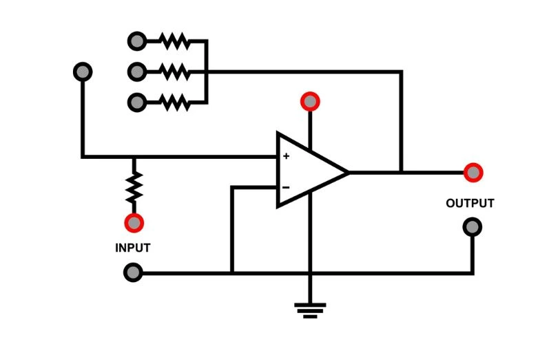
Designing a non-inverting amplifier circuit is an intriguing journey where each component is integral. The meticulous selection of resistors and op-amp components is essential to ensure the stability and performance of the amplifier.
Selecting Resistors
The choice of resistors R1 and R2 determines the gain of the non-inverting amplifier. By following the formula (1 + R2/R1), one can calculate the desired gain of the amplifier. It’s crucial to carefully choose these resistor values to achieve the desired amplification while maintaining stability and preventing oscillations in the circuit.
For example, selecting higher values for both R1 and R2 can result in increased input impedance, reducing the load on the source – particularly useful when interfacing with high-impedance sources like sensors or transducers. Conversely, lower resistor values can lead to an increased bandwidth and improved noise performance, ideal for signal conditioning applications.
Component Sizing
Unlike resistor selection, sizing the op-amp and resistor values requires meticulous attention. The operational amplifier (op-amp) model and resistor values should be carefully calculated to achieve the desired gain without compromising input and output impedance. Ensuring that the input impedance is high and the output impedance is low is crucial to prevent signal degradation and maintain overall circuit stability.
In addition, component sizing should also account for factors such as temperature drift, bias current, and offset voltage. These factors can introduce inaccuracies in the amplification process if not accounted for during the component selection phase. Therefore, it’s imperative to consider these aspects to attain precise amplification results.
Diagram Illustration
Visual representation of the circuit design through detailed diagrams proves instrumental in understanding the physical layout and connections of the components within the non-inverting amplifier circuit. A well-illustrated diagram not only aids in comprehension but also serves as a reference point for troubleshooting and further modifications.
For instance, including labels for each component and their specific values in the diagram clarifies the connections and facilitates easy understanding for beginners and enthusiasts alike. Furthermore, a graphical representation assists in identifying potential areas for improvement or modification within the circuit design.
Designing a non-inverting amplifier circuit involves carefully balancing component selection, sizing, and visual representation. By paying close attention to resistor selection and op-amp sizing and utilizing detailed diagrams, one can craft a robust, non-inverting amplifier circuit that meets specific amplification requirements while ensuring stability and performance.
The next section will delve into methods for optimizing gain adjustment to elevate your amplifier’s performance.
Gain Adjustment for Optimal Performance
Once you’ve designed your non-inverting amplifier circuit, the next step is to adjust the gain for optimal performance. The gain of an amplifier determines how much the output signal increases in amplitude compared to the input signal. This adjustment is crucial as it impacts the overall functionality and efficiency of the amplifier. Let’s delve into this adjustment process and why it’s essential.
Calculating Gain
When adjusting the gain of your non-inverting amplifier, it’s vital to calculate the specific amplification factor required for your application. The amplification factor, denoted as Av, can be calculated using a simple formula: Av = 1 + (Rf / R1). Rf represents the feedback resistor, and R1 is the input resistor. By manipulating these resistor values, you can achieve the desired level of amplification necessary for your circuit.
You can tailor the gain to suit various applications by carefully manipulating these resistor values. For instance, you might need a higher gain to drive speakers in audio amplification. At the same time, you may require a precise and smaller gain adjustment for accurate sensor readings in sensor interfaces. Calculating these adjustments ensures that the amplifier operates within the desired voltage ranges, effectively boosting the input signals without distortion.
To further understand this process, let’s look at some real-life scenarios where gain adjustments are essential. For instance, you might need a higher gain in audio amplification to drive loudspeakers and deliver clear sound quality adequately. On the other hand, in sensor interface circuits, precision is key, and a smaller gain adjustment may be necessary to ensure an accurate interpretation of sensor data.
For example, when designing an instrumentation circuit for measuring small signal voltages accurately, a precise gain adjustment is imperative to maintain the fidelity of the measurements without adding noise or distortion. Understanding and implementing varied gain adjustments based on specific application requirements is vital in achieving optimal circuit performance in each scenario.
Understanding how to calculate and implement gain adjustments precisely allows you to optimize your non-inverting amplifier circuit according to specific application needs. Let’s explore the practical steps in fine-tuning these adjustments for real-life scenarios.
Importance of Input Impedance

Impedance is a term commonly used in audio systems and electrical devices, and for a good reason. Simply put, it acts as a gatekeeper, determining how much your device resists or allows the flow of electric current. In the context of non-inverting amplifiers, input impedance plays a vital role in maintaining the integrity of signals coming into the amplifier.
Imagine you have a musical instrument you want to plug into an amplifier. The instrument is designed to put out a certain signal, and you want all of that signal to go into the amplifier without any interference. Now, if the amplifier has low input impedance, it’s like trying to pour water from a small pipe into a big bucket—you’re not utilizing the full potential of your instrument’s output. On the other hand, high input impedance means it’s like pouring water from a small pipe into a small bucket—everything goes exactly where it’s intended to go.
Preventing Loading Effects
Input impedance serves as a welcoming door for incoming signals. A high input impedance amplifier draws very little current from the source and does not interfere with or load down the source. This means the signal source doesn’t have to work hard or lose quality to ensure its signal reaches its destination without losing anything in transit.
For instance, if your guitar sends out 10 millivolts of signal and your amplifier’s input impedance is 1 megaohm (1 million ohms), nearly all of that precious signal gets through unharmed. Conversely, if your amplifier had low input impedance (say 1kohm), more current would be drawn, and thus, more signal power dissipated inside the source, resulting in the weakened output signal and overall degradation of sound quality.
It’s important to note that while low input impedance can lead to loading effects on your input signal source, excessively high input impedance can cause noise issues due to increased susceptibility to external interference.
Finding this sweet spot for input impedance is crucial for maintaining signal integrity and ensuring that our non-inverting amplifiers deliver accurate and faithful representations of the original signal.
Calculations and Practical Applications
The practical application of understanding input impedance ensures that our signal source doesn’t undergo any unnecessary compromising. It’s about creating an environment where electrical current can flow with minimal resistance and maximum potential.
Think of it as building good roads—when traffic flows smoothly and efficiently, everyone reaches their destination without being slowed down or facing any obstacles. Similarly, proper input impedance ensures signals travel through our circuits smoothly and without impediments.
Now that we understand why input impedance is crucial let’s explore how we calculate it and its practical impact on signal integrity with real-world examples.
Handling Source and Load Impedances
When dealing with non-inverting amplifier circuits, it’s not just about the gain or the input impedance; source and load impedances play a critical role in maintaining signal integrity and overall performance. The source impedance is the resistance or impedance seen by the amplifier at its input. In contrast, the load impedance is the resistance or impedance presented to the amplifier at its output.
Source Impedance Considerations
The source impedance can affect the accuracy of your amplifier’s output, especially when interfacing with a sensor or microphone with significant internal resistance. If the source impedance is high compared to the amplifier’s input impedance, it can lead to signal loss and distortion. Ensuring that the source impedance is much lower than the input impedance of the non-inverting amplifier is crucial to mitigate this. One technique to achieve this is using a buffer between the source and the amplifier. A buffer with high input impedance and low output impedance effectively isolates the source from loading effects and ensures that the signal remains intact.
For instance, let’s consider a scenario where the non-inverting amplifier connects to a sensor with a relatively high internal resistance. Without properly considering source impedance, the accuracy of the amplified signal can be compromised. By introducing a buffer with high input impedance, the sensor’s signal remains unaffected by the loading effects of the amplifier, preserving its fidelity.
Load Impedance Effects
On the other hand, when it comes to the load impedance, it directly influences the signal delivered by the amplifier to subsequent stages or loads, such as other amplifiers or filters. Ensuring compatibility between the output impedance of the non-inverting amplifier and the input impedance of the next stage is vital for maintaining signal fidelity and preventing signal degradation.
If the amplifier’s output impedance exceeds the load impedance, it can cause signal loss and distortion by drawing excessive current from the output stage. However, if it’s too high, it can lead to reduced power transfer efficiency and affect frequency response.
Strategies for Maintaining Signal Fidelity
To maintain signal fidelity and ensure seamless signal transfer between stages, properly matching the output impedance of the non-inverting amplifier with subsequent loads or employing buffering techniques can significantly enhance overall system performance.
Understanding these potential pitfalls associated with source and load impedances provides valuable insights into optimizing non-inverting amplifier circuits for superior performance and reliability.
Overcoming Offsets and Common Issues
Even after optimizing the input impedance for your non-inverting amplifier circuit, you may encounter common issues impacting signal processing. One such issue is input offset voltage, which compromises amplification accuracy and precision. It creates errors by introducing unwanted constant voltage at the input terminals of the operational amplifier, leading to inaccuracies and signal distortions.
To mitigate input offset voltage and ensure precise amplification, techniques exist to nullify this offset voltage. One such method is “offset nulling,” which involves actively adjusting voltages within the amplifier circuit to cancel any undesired offset voltage. This allows for precise adjustments to counteract the effects of input offset voltage, resulting in more accurate signal amplification and processing.
Practical Examples and Solutions
If you’re experiencing an input offset voltage issue, using a potentiometer or other adjustable components to calibrate and balance the input voltages can nullify the offset voltage, achieving a more accurate and stable output signal. By implementing practical solutions like these, electronics enthusiasts can address input offset voltage concerns and elevate the performance of their non-inverting amplifier circuits.
Beyond offset voltage management, additional common problems can arise in non-inverting amplifier circuits, including noise, distortion, and stability concerns. These issues significantly impact the fidelity and reliability of signal processing, requiring effective mitigation strategies to ensure optimal circuit performance.
Proper attention to grounding techniques, signal shielding, and component placement is crucial for minimizing interference and maintaining signal integrity when addressing noise and distortion in non-inverting amplifier circuits. Additionally, employing high-quality components with low noise characteristics can reduce undesirable noise and distortion in amplified signals.
Regarding stability concerns, careful consideration of feedback network design, adequate bypassing, and appropriate compensation techniques can enhance the stability and robustness of non-inverting amplifier circuits.
By delving into practical examples and addressing these prevalent challenges head-on, electronics enthusiasts can empower themselves with the knowledge and skills needed to overcome offsets and common issues in non-inverting amplifier circuits, thereby elevating the quality and reliability of their electronic designs.
Discover more about amplifiers and enhance your understanding of electronics by visiting our site about amplifiers.
