

Understanding the Characteristics of RC Phase Shift Oscillator
An RC phase shift oscillator is a unique electronic circuit with a sine wave output. It uses a special mechanism called phase shift, introduced by an RC network to keep oscillations going. Comprised of an inverted operational amplifier and several RC networks forming a ladder-like setup, it achieves a needed 180-degree phase shift, delivering continuous oscillations. Let’s dive deeper into the world of such oscillators.
An RC phase shift oscillator utilizes resistors and capacitors to create a 360-degree total phase shift in the feedback signal, facilitating sustained oscillation. The oscillator generates a stable output waveform by carefully selecting resistor and capacitor values to achieve specific phase shifts at the desired frequency.
Unveiling RC Phase Shift Oscillator
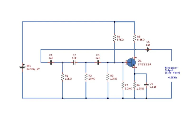
In electronics, the RC phase shift oscillator harnesses the intriguing dynamics of an RC network to initiate and sustain waves within electronic circuits. Like a magic hand causing ripples in water, the RC network catalyzes creating and propagating waves through the circuit.
The Analogy of Phase Shift
Analogous to the initial ripple in water, the concept of phase shift is fundamental to this oscillator. It denotes the timing and strength required to induce waves to traverse the circuit. This crucial effect must be precisely replicated through electronic components to ensure waves move at the optimal speed and intensity.
Energizing the Circuit
Imagine a playground roundabout propelled into motion by well-timed pushes. The RC network plays the role of the push, injecting energy into the wave at precisely the right moments. Once initiated, the wave takes control and continues circulating, akin to the roundabout’s momentum after ceasing to push.
Balancing Act
Maintaining a harmonious balance in the circuit, akin to synchronizing pushes on the roundabout, is crucial. Each component’s contribution to the phase shift must align perfectly. Any deviation, like mistimed pushes, can disrupt the smooth continuity of the wave’s movement.
Ladder Configuration
To ensure consistent and robust wave propagation, multiple RC stages are interconnected in a “ladder configuration.” This arrangement guarantees ample pushes or contributions to sustain the waves, preventing their premature decay.
Each Stage’s Role in the Circuit
Visualize each person contributing to the pushing of the roundabout as representing a stage in the RC network. Each stage must exert its influence at distinct intervals, avoiding interference with others. Much like in the roundabout scenario, simultaneous pushing by all stages is counterproductive.
Achieving a 180-degree Phase Shift
The culmination of precisely timed contributions from each stage results in a 180-degree phase shift. This collective effort ensures the circuit has the necessary components to sustain the continuous circulation of waves, producing a stable and precise sine wave output.
By exploring the operational intricacies of an RC phase shift oscillator and drawing parallels with relatable examples, a deeper understanding of these complex circuits emerges. This comprehension allows an enhanced appreciation of their role in generating accurate sine wave outputs within electronics.
Crafting Your Own RC Phase Shift Oscillator
Crafting your RC phase shift oscillator can be an engaging project for electronics enthusiasts. It involves selecting the right components, configuring the operational amplifier, and building the circuit. Let’s break down each step to ensure a clear understanding of the process.
Step 1: Selecting Components
When selecting components for your RC phase shift oscillator, resistors, and capacitor values are crucial in determining oscillation frequency. Different combinations yield various frequencies, tailoring the oscillator to specific requirements. Additionally, designing the feedback network with three RC stages introduces the required phase shift for sustained oscillations. This is essential for ensuring stable and consistent oscillations over time.
Step 2: Configuring the Operational Amplifier
The operational amplifier (op-amp) is a fundamental RC phase shift oscillator circuit component. Connecting the op-amp to the inverting mode is important to achieve the desired phase shift and feedback characteristics when configuring the op-amp. Setting the gain of the op-amp is crucial, as it helps maintain a stable amplitude for the output signal—ensuring that the oscillations produced by the circuit are reliable and consistent.
Step 3: Building the Circuit
Assembling the chosen resistors, capacitors, and operational amplifiers on a breadboard or printed circuit board (PCB) is the final step in crafting your RC phase shift oscillator. Following specific design requirements, such as placement and connectivity, is vital to ensure the circuit functions as intended. Building the circuit accurately according to these specifications will help achieve the desired frequency characteristics and ensure optimal performance.
By comprehending these steps and investing care in crafting your RC phase shift oscillator, you can gain valuable hands-on experience in electronics while creating a functional and versatile circuit.
Decoding the Oscillation Frequency
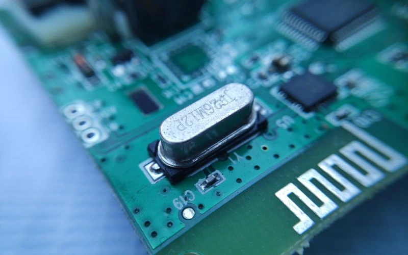
The frequency of oscillations in an RC phase shift oscillator is crucial for its performance, determining how fast the oscillator produces its output waveform, directly impacting its usability. You must understand and use a specific formula to calculate the frequency. The formula to determine the frequency of oscillations in an RC phase shift oscillator is:
f = 1 / (2 * π * R * C * n)
Here’s what each variable in the formula represents:
- f: The frequency of oscillation in Hertz (Hz).
- R: The resistance in ohms (Ω).
- C: The capacitance in farads (F).
- n: The number of RC stages.
The significance of this formula lies in its ability to provide a straightforward method for determining the frequency of oscillations based on the values of resistance, capacitance, and the number of feedback stages. This formula is crucial for achieving the desired frequency response when designing an RC phase shift oscillator.
It’s important to note that adjusting the resistance or capacitance values can directly impact the oscillation frequency. Increasing or reducing the number of RC stages will also influence the output frequency. This flexibility enables you to tailor the oscillator’s frequency characteristics to suit specific application requirements.
For instance, if you want your RC phase shift oscillator to produce a sinusoidal signal at a particular frequency for audio applications, such as music synthesis or sound processing, accurately calculating and implementing the right resistance, capacitance, and feedback stages is paramount.
Utilizing this formula and understanding its implications ensures that the designed oscillator operates effectively within the desired frequency range. For audio applications, signal generation, or any other use case requiring a stable sinusoidal waveform at a specific frequency, mastering this fundamental aspect opens up a world of possibilities for precise oscillator design.
Mastering this fundamental aspect empowers you to finely tune your RC phase shift oscillator according to your unique specifications. Next, we’ll explore further insights into leveraging this understanding to optimize your oscillator’s performance within targeted frequency ranges.
Choosing Components For Optimal Performance
Choosing components is crucial when bringing out the best in your RC phase shift oscillator. High-quality resistors and capacitors with low tolerance are like the foundation of a sturdy building – they provide stability and accuracy in the oscillation frequency.
Low-Tolerant Component
A low-tolerance component means its actual value stays close to its specified value. This is important because it helps reduce unwanted variability in the oscillator’s frequency. Imagine trying to tune a guitar when the tuning pegs keep slipping – it’s much easier when they are precise and hold their position. Similarly, precision components contribute to reducing frequency drift and maintaining consistent performance over time.
High-Quality Resistor
Consider a high-quality resistor; its resistance will remain stable over time and temperature changes, minimizing any unwanted alterations in the oscillator’s output frequency due to external factors. Likewise, capacitors with low tolerance ensure that the phase shift they provide remains uniform, contributing to the stability and predictability of the oscillator’s frequency.
Operating Conditions and Environmental Factors
Furthermore, as we strive for precision and consistency in our oscillator’s performance, we must consider the operating conditions and environmental factors that may impact the components’ behavior. Different capacitor types may be more suitable for specific frequency ranges, and certain resistors may offer superior stability under varying temperatures.
Let’s delve into practical considerations for selecting these critical components to ensure our RC phase shift oscillator operates at its peak efficiency.
Harnessing the Power of Feedback Network
Having explored the pivotal role of the feedback network in an RC phase shift oscillator, let’s now delve into how its implementation influences the overall frequency characteristics of this unique electronic circuit.
Interpreting Output Voltage Results
Interpreting output voltage results in RC phase shift oscillators is foundational for evaluating the circuit’s performance. This involves a detailed analysis of the output voltage waveform, extracting crucial information about amplitude and frequency, and providing insights into the oscillator’s overall behavior.
Significance of Amplitude and Frequency
Understanding the significance of amplitude (peak voltage) and frequency in the context of RC phase shift oscillators is essential. Amplitude represents the strength of oscillations, while frequency indicates the number of cycles within a given time. Both parameters are key indicators of the oscillator’s efficiency in generating and sustaining oscillations.
Role of Oscilloscopes in Analysis
Oscilloscopes play a pivotal role in assessing RC phase shift oscillator performance. These instruments give engineers a precise means of visualizing and measuring electrical waveforms. Connecting the oscilloscope to the oscillator’s output terminals facilitates in-depth analysis, allowing professionals to observe peak amplitudes, oscillation frequencies, and other critical waveform characteristics.
Crucial Output Voltage Parameters
The interpretation process involves scrutinizing various aspects of the waveform. Key parameters include peak-to-peak voltages, revealing the waveform’s maximum excursion, and root mean square (RMS) voltages, offering an average intensity measure. Assessing the periodicity and regularity of oscillations provides valuable insights into stability and frequency consistency, which are critical for reliable circuit operation.
Utilizing Oscilloscope for Diagnostics and Optimization
Electronic electronics professionals gain a diagnostic and optimization tool by mastering interpreting output voltage results using an oscilloscope. This capability empowers them to make informed decisions, precise adjustments, and fine-tuning to ensure optimal functionality and reliability of RC phase shift oscillators.
Summary of Interpretation Process
Interpreting output voltage is vital for engineers and technicians handling RC phase shift oscillators. Detailed analysis using oscilloscopes offers actionable insights, enhancing circuit performance and reliability.
With a grasp of how to interpret output voltage results under our belt, let’s now turn our attention to exploring real-world applications where RC phase shift oscillators shine.
Exploring the Practical Applications of RC Phase Shift Oscillator
RC phase shift oscillators are akin to versatile tools in electronics. Similar to a Swiss army knife that offers various functionalities, these oscillators find uses in different electronic systems, rendering them an essential part of audio equipment and signal generators.
Let’s start with their applications in audio signal generation. From producing the standard frequencies used to calibrate audio systems to creating test tones for loudspeakers and headphones, RC phase shift oscillators lie at the heart of these vital operations.
These oscillators also serve as the primary component in function generators, instruments commonly used in electronic testing. Function generators create sine, square, and triangle waves, which are essential for testing electrical equipment to ensure proper functionality. Credit may go to RC phase shift oscillators when devices pass quality tests seamlessly.
Moving on to tone control circuits in audio equipment, these oscillators play a pivotal role in ensuring the production and control of high-quality sound. By regulating tone balance, they enable the amplification of certain frequencies and maintain a clear and balanced audio output.
While these applications primarily align with audio systems, RC phase shift oscillators are equally important in frequency-sensitive electronic applications such as phase-locked loops. These loops are instrumental for digital communications systems’ demodulation (recovering information from a modulated wave) and clock recovery.
Tone Generation
| Application | Function |
| Audio Signal Generation | Calibration and test tones for audio systems |
| Function Generators | Producing various waveforms for electronic testing |
Tone Control Circuits
| Application | Function |
| Audio Equipment | Regulating tone balance for clear sound output |
Frequency-Sensitive Applications
| Application | Function |
| Phase-Locked Loops | Demodulation and clock recovery in digital communications |
Understanding these applications helps us appreciate the versatility and relevance of RC phase shift oscillators in various electronic systems. When you reflect, without them, numerous electronics pivotal for daily work or entertainment might lack their current reliability. Appreciate the inconspicuous role of RC phase shift oscillators in ensuring seamless communication and clear sound quality.
To learn more about oscillator circuits, including RC phase shift oscillators, visit Oscillator Circuits on our website for insightful articles and resources.
