

Differences Between NPN and PNP Transistors
When exploring transistors, you’ll encounter NPN and PNP types, each with unique characteristics. NPN transistors have two n-type and one p-type layer, while PNP transistors have the reverse. This structural difference affects how current flows and influences their specific applications in circuits. Understanding these variations is crucial for selecting the appropriate transistor for your project. Curious about how these differences impact their performance and use? Let’s explore further.
Key Takeaways
- NPN transistors have two n-type layers, while PNP transistors have two p-type layers.
- NPN transistors use electrons as majority carriers; PNP transistors use holes.
- NPN requires a positive base-emitter voltage; PNP requires a negative base-emitter voltage.
- NPN transistors allow collector-to-emitter current flow; PNP transistors enable emitter-to-collector current flow.
- NPN transistors are preferred for high-speed applications; PNP transistors suit high-side switching and logic circuits.
Structure and Components of NPN and PNP Transistors
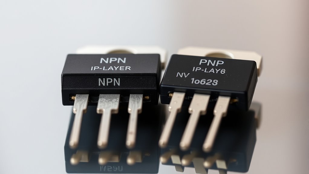
Transistors, the building blocks of modern electronics, come in two main types: NPN and PNP.
The structure of NPN transistors involves two n-type semiconductor layers with a p-type layer sandwiched in between. In contrast, PNP transistors feature two p-type layers with a single n-type layer sandwiched between them.
The majority charge carriers differ: electrons for NPN transistors and holes for PNP transistors. The emitter in an NPN transistor is connected to the negative terminal, while in a PNP transistor, it is connected to the positive terminal.
The base-emitter junction in NPN transistors is forward-biased with a positive voltage, whereas in PNP transistors, it’s forward-biased with a negative voltage.
These configurations are pivotal for controlling the flow of charge.
Current Flow Characteristics in Transistors
When examining current flow characteristics, you’ll notice that NPN and PNP transistors operate quite differently.
In NPN transistors, current flows from the collector to the emitter, driven by a positive voltage at the collector; conversely, PNP transistors require current to flow from the emitter to the collector, needing a positive voltage at the emitter.
Understanding these dynamics helps you determine which transistor type best suits your circuit needs.
NPN Current Flow Direction
Understanding the current flow direction in NPN transistors is essential to mastering their operation in electronic circuits.
In an NPN transistor, current flows from the collector to the emitter when the base-emitter junction is forward-biased with a positive voltage. This setup enables a small base current to control a much larger collector current.
You’ll notice in circuit diagrams that an outward arrow on the emitter represents this direction. The base current is vital because it allows the larger current to flow through the collector-emitter path, provided the base-emitter voltage is sufficient.
However, if the base-emitter junction doesn’t receive adequate voltage, the transistor enters the cutoff region, preventing any current from flowing between the collector and emitter.
PNP Current Flow Dynamics
In PNP transistors, the current flow dynamics differ from those of NPN transistors due to their unique configuration. Current flows from the emitter to the collector, and the base must be at a lower voltage than the emitter for this process to happen effectively.
PNP transistors primarily use holes as their charge carriers, unlike NPN transistors, which rely on electrons. By applying a small negative voltage to the base-emitter junction, you forward-bias the junction, enabling significant current flow from the emitter to the collector.
Typically, the load in a PNP setup connects between the collector and ground. This configuration is beneficial in industrial control applications, where the sensed stimulus at the base provides a positive output.
Understanding these dynamics is essential for using PNP transistors effectively.
Operating Regions of Bipolar Junction Transistors
Although transistors may seem complex at first, understanding the operating regions of Bipolar Junction Transistors (BJTs) is crucial for grasping their role in circuits.
Both NPN and PNP transistors operate in three key regions: active, cutoff, and saturation. In the active region, the base-emitter junction is forward-biased, and the base-collector junction is reverse-biased, allowing BJTs to amplify signals.
In the cutoff region, both junctions are reverse-biased, resulting in no current flow and effectively turning the transistor off.
When in the saturation region, both junctions are forward-bias, resulting in maximum current flow between the collector and emitter, functioning as a closed switch.
Understanding these regions is crucial for effective circuit design and analysis, as they significantly influence transistor performance in amplifying or switching tasks.
Biasing Requirements for NPN and PNP Transistors
When delving into the world of BJTs, understanding the biasing requirements for NPN and PNP transistors is crucial.
For NPN transistors, a positive voltage at the base-emitter junction is required to forward-bias it, allowing current to flow from the collector to the emitter. The base must be at a higher potential than the emitter, typically above a certain cutoff value, to achieve the desired operational regions.
In contrast, PNP transistors require a negative voltage at the base-emitter junction for forward-biasing, guiding current from the emitter to the collector. Here, the base needs to be at a lower potential than the emitter.
Understanding these biasing requirements is vital, as they directly influence the active, cutoff, and saturation regions, which are crucial for circuit design.
Amplification Capabilities of NPN and PNP Transistors
When you’re considering the amplification capabilities of NPN and PNP transistors, it’s essential to understand their current flow dynamics.
NPN transistors excel at amplifying positive signals, making them ideal for low-power applications, while PNP transistors handle negative signals for high-speed tasks.
Your choice between them should align with your circuit design needs, such as voltage levels and switching preferences.
Current Flow Dynamics
Understanding current flow dynamics is essential when exploring the amplification capabilities of NPN and PNP transistors.
In NPN transistors, current flows from the collector to the emitter. Applying a positive voltage to the base allows a small base current to control a larger current flow, enabling effective amplification.
Conversely, PNP transistors require a positive voltage at the base, causing current to flow from the collector to the emitter. This setup also facilitates amplification, though it operates differently from NPN transistors.
The current gain (β) for both transistor types, typically ranging from 100 to 300, signifies their ability to amplify signals by comparing the collector current to the base current.
NPN transistors, favored for high-speed applications, offer faster electron mobility, enhancing response times.
Signal Amplification Process
The signal amplification process is central to the function of both NPN and PNP transistors.
You’ll find that NPN transistors amplify positive signals by allowing a larger collector current to flow from collector to emitter, driven by a smaller base current. Conversely, PNP transistors require a negative base voltage to enable current flow from the emitter to the collector.
In the active region, both types efficiently control current flow: NPN transistors use electrons, while PNP transistors utilize holes.
The current gain (β), which is the ratio of collector current to base current, typically ranges from 100 to 300.
NPN transistors are often preferred for high-speed applications due to faster electron mobility, making them ideal for effective signal amplification.
Circuit Design Implications
Although NPN transistors are often favored for their superior amplification capabilities, both NPN and PNP types have distinct roles in circuit design.
In amplification applications, the choice between NPN and PNP depends on the desired current flow and output configuration. NPN transistors excel in sinking output, efficiently controlling a larger collector-emitter current with a small base current. This makes them ideal for high-speed switching circuits due to their higher current-carrying capacity and faster electron mobility.
On the other hand, PNP transistors are adept at sourcing output, which is advantageous in high-side switching applications where a positive output is needed.
Switching Functions in Electronic Circuits
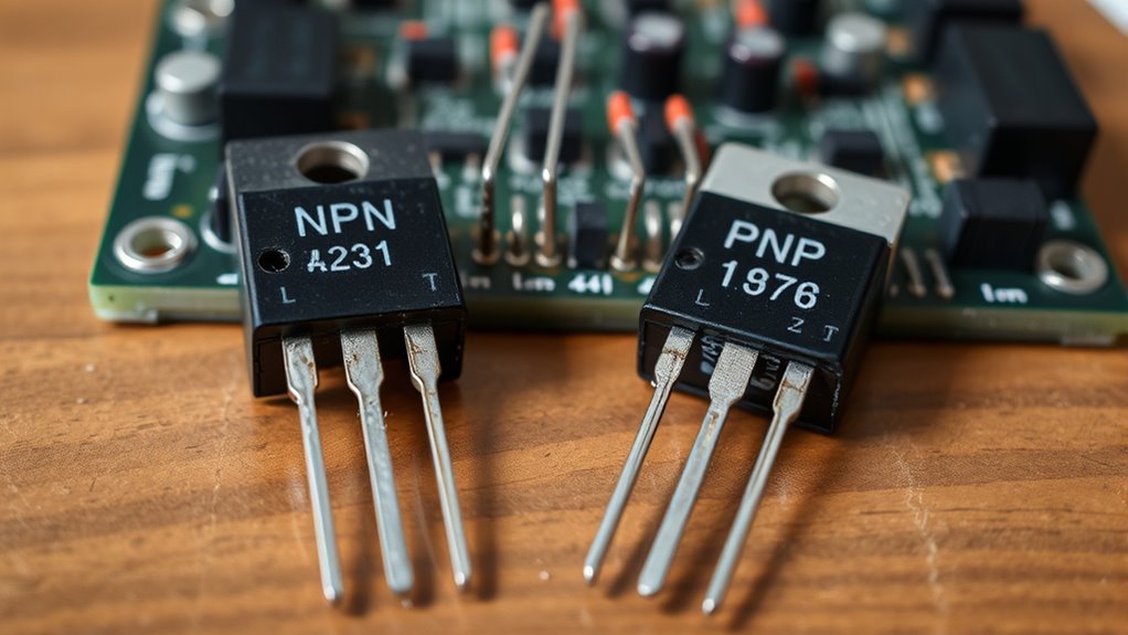
When considering switching functions in electronic circuits, NPN and PNP transistors play pivotal roles with distinct characteristics.
NPN transistors act as low-side switches, directing current flow from the collector to the emitter. In contrast, PNP transistors serve as high-side switches, channeling current from the emitter to the collector.
In active mode, an NPN transistor requires a positive base voltage to forward-bias the base-emitter junction, whereas a PNP needs a negative base voltage for similar current flow.
The output configuration differs as NPN transistors “sink” current from the load, and PNP transistors “source” current to it.
Advantages of NPN Transistors in Low-Power Applications
Switching functions in electronic circuits rely heavily on the unique qualities of NPN transistors, especially in low-power applications.
You’ll find that these transistors excel due to their higher current-carrying capacity, allowing efficient signal amplification even at lower voltages. This makes them perfect for low-power environments.
Thanks to their electron-based construction, NPN transistors switch faster and perform better in these circuits. With a lower turn-on voltage than PNP transistors, they’re ideal for low-voltage applications, ensuring energy efficiency.
In digital logic circuits and low-power amplifiers, NPN transistors provide reliable and cost-effective solutions, widely adopted in consumer electronics.
For instance, a common NPN transistor, such as the 2N3904, handles up to 200 mA, making it ideal for low-power tasks.
Benefits of PNP Transistors in High-Speed Operations
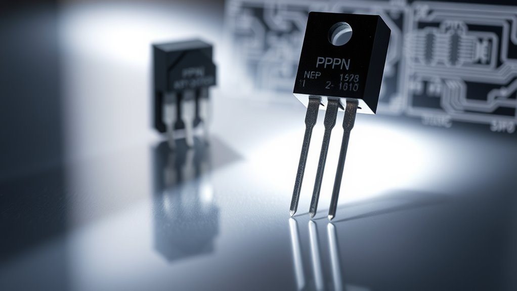
In high-speed operations, PNP transistors offer distinct advantages that make them indispensable in many electronic applications. They typically have lower turn-on voltages, which means faster switching speeds in high-speed applications. This is vital for achieving efficient performance.
PNP transistors are adept at current sourcing, making them ideal for high-side switching in high-speed circuits. Their use in complementary push-pull amplifier configurations, alongside NPN transistors, guarantees efficient signal switching and enhances overall performance.
Furthermore, in high-frequency applications, the majority of charge carriers (holes) in PNP transistors lead to quicker response times. In digital logic circuits, the design of PNP transistors facilitates faster switching times, making them well-suited for high-speed logic applications in integrated circuits.
Common Applications of NPN Transistors
While PNP transistors excel in high-speed operations, NPN transistors bring their valuable contributions to various electronic applications. They’re commonly used in audio and RF amplifier circuits, efficiently boosting weak signals. In digital logic circuits, NPN transistors serve as essential switches in logic gates and flip-flops, ensuring high-speed operations with minimal power consumption.
In power electronics, NPN transistors stabilize output voltages in voltage regulators and power supply circuits. Their faster electron mobility makes them ideal for high-speed switching applications, enhancing circuit performance. The versatility of NPN transistors shines brightly in proximity sensors and PLCs, allowing for easy interfacing with microcontrollers for low-voltage outputs.
| Application | Benefit | Emotion |
|---|---|---|
| Amplifier Circuits | Efficient Signal Amplification | Reliability |
| Digital Logic Circuits | High-Speed Operations | Innovation |
| Power Electronics | Stable Voltage Regulation | Trust |
Practical Uses of PNP Transistors
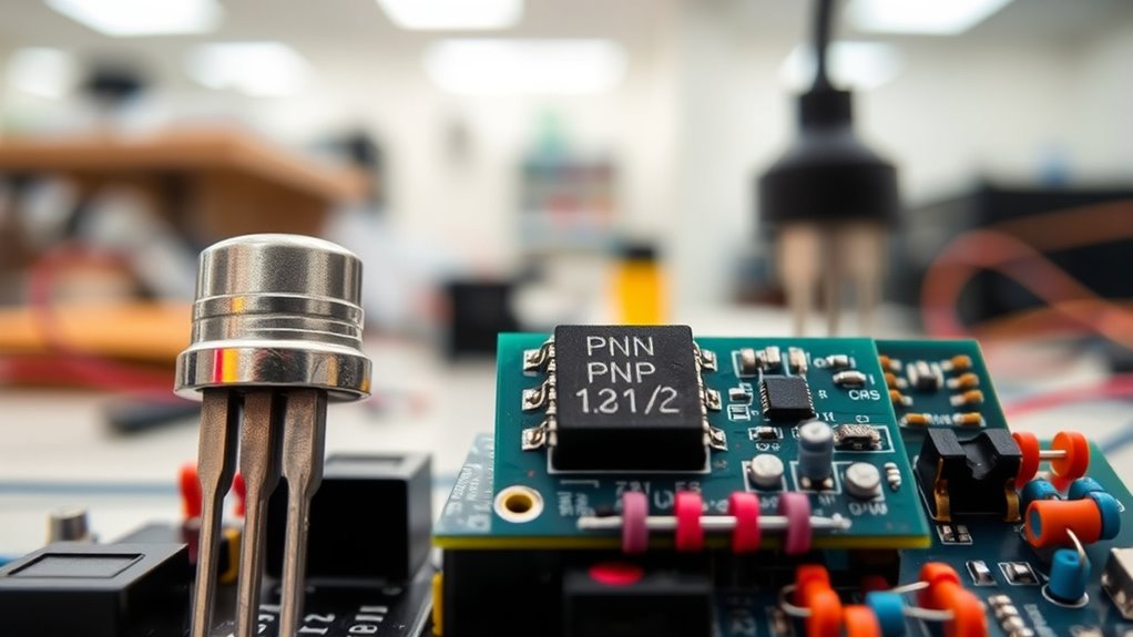
Although NPN transistors often take center stage in many applications, PNP transistors also have their own set of practical uses that shouldn’t be overlooked.
In high-side switching, PNP transistors are ideal as they connect the load between the collector and ground, providing a positive voltage output.
In industrial automation, they act as sensing sensors, sending positive signals to control devices when the base is negatively biased.
For signal amplification, PNP transistors enhance efficiency when paired with NPN transistors in complementary push-pull amplifier circuits.
They also play a significant role in voltage regulators, maintaining a stable output by sourcing current as needed.
Their ability to handle high-voltage signals makes them perfect for interfacing with industrial controls and instrumentation systems.
Conclusion
In understanding NPN and PNP transistors, you’ve explored their structural and operational differences. NPN transistors, with their current flowing from the collector to the emitter, are ideal for low-power applications. On the other hand, PNP transistors, with current flowing from emitter to collector, excel in high-speed operations. Whether you’re focusing on biasing requirements or amplification capabilities, knowing these differences helps you choose the right transistor for your project, ensuring efficient performance tailored to specific needs.
FAQs
1. What Is the Difference Between NPN and PNP Transistors?
You should know that NPN transistors use electrons for current flow, requiring a positive base-emitter voltage. In contrast, PNP transistors use holes and require a negative base-emitter voltage, which affects their application in circuits.
2. What is the Difference Between PNP and NPN models?
You’re asking about the difference between PNP and NPN models. Focus on the current flow and biasing requirements. NPN models conduct when the base is positive, while PNP models conduct with a negative base voltage.
3. Why Do We Use NPN Over PNP Transistors?
You’d choose NPN transistors over PNP for faster switching speeds, higher current capacity, and cost-effective manufacturing. They simplify circuit designs, prevent ground loops, and are better suited for applications requiring negative signals, thereby enhancing overall efficiency.
4. How Can You Distinguish Between NPN and PNP Transistors by Using a Multimeter?
You can distinguish NPN and PNP transistors with a multimeter in diode mode. For NPN, connect the positive lead to the base. For PNP, switch the leads. A 0.6 to 0.7V drop confirms each type.
