

Difference Between VCO and PLL: Key Concepts & Comparison
You’ve likely come across Voltage-Controlled Oscillators (VCOs) and Phase-Locked Loops (PLLs) in your exploration of electronics. At first glance, they might seem similar because both involve frequency control. However, understanding their core functions and applications reveals distinct differences. While a VCO directly generates frequencies based on input voltage, a PLL aligns signals with precision. Curious about how these differences impact performance in real-world applications? Let’s explore further.
Key Takeaways
- A VCO generates a frequency based on input voltage, while a PLL synchronizes this frequency with a reference signal.
- VCOs are standalone frequency generators; PLLs include VCOs within a feedback loop for phase synchronization.
- PLLs offer improved stability by continuously adjusting frequency to minimize phase errors, unlike VCOs.
- VCOs are quicker to respond to voltage changes, whereas PLLs focus on precise frequency and phase alignment.
- PLLs have lower phase noise due to their feedback mechanisms than standalone VCOs.
Overview of Voltage-Controlled Oscillators (VCOs)
Voltage-Controlled Oscillators (VCOs) are integral to modern electronic systems. They generate a periodic output signal whose frequency is proportional to an input tuning voltage. This capability allows you to achieve a wide frequency range, making VCOs essential in applications like frequency synthesizers.
VCOs are vital in phase-locked loops (PLLs), as they help maintain precise output frequencies by adjusting to varying control voltages.
The quality factor (Q) of a VCO greatly affects its phase noise characteristics; a higher Q results in lower phase noise, albeit with a narrower frequency range.
For example, the HMC507 offers superior phase noise at 115 dBc/Hz, whereas the HMC586 provides broader coverage with a trade-off in phase noise at 100 dBc/Hz.
Understanding Phase-Locked Loops (PLLs)
Understanding Phase-Locked Loops (PLLs), you’ll find that their key components include the phase detector, low-pass filter, and voltage-controlled oscillator (VCO).
The phase detector compares the input and output phases, generating an error signal that indicates any phase difference.
The low-pass filter then smooths this error signal, ensuring that the VCO can adjust the output frequency precisely to maintain synchronization.
Key PLL Components
A Phase-Locked Loop (PLL) isn’t just a complex electronic system—it’s a harmonious interplay of key components working in unison to lock and synchronize signal phases.
At its core, the phase detector compares the phases of the reference signal and the VCO output. It generates an error signal that reflects the phase difference. This error signal is essential, indicating the necessary adjustments for synchronization.
Next, the low-pass filter processes the error signal, eliminating high-frequency noise and ensuring a smooth control voltage for the VCO. The VCO then uses this control voltage to adjust its output frequency, allowing for precise frequency synthesis and rapid response to changes.
With these components, PLLs maintain stable output frequency and phase alignment.
Function of Phase Detector
While diving into the intricate workings of Phase-Locked Loops (PLLs), the phase detector plays a vital role. It compares the phase of an input signal with the output signal from the VCO. By determining the phase difference, the phase detector generates an error signal. This signal indicates how much the output frequency should adjust, guaranteeing the PLL maintains synchronization, a fundamental aspect for any frequency synthesizer.
The phase detector produces high and low signals based on these phase comparisons. These signals control the charge pump, which tweaks the VCO’s tuning voltage. Consequently, the phase detector’s performance greatly impacts the PLL’s stability and response time, influencing applications like clock recovery and frequency modulation.
Its real-time feedback guarantees continuous and precise control loop operation.
Low-Pass Filter Role
When diving into the intricacies of Phase-Locked Loops (PLLs), you’ll find that the low-pass filter plays an integral role in refining the system’s performance. It processes the error signal from the phase detector, eliminating high-frequency noise to guarantee a smooth control voltage for the VCO.
The low-pass filter stabilizes the control voltage, helping the PLL achieve a stable and precise output frequency. Its cutoff frequency is vital, influencing the PLL’s response time and overall loop stability.
Additionally, low-pass filters prevent unnecessary fluctuations, enhancing the PLL’s ability to maintain lock with the reference signal. Their design impacts jitter and phase noise characteristics, making them indispensable in high-performance applications where precision is paramount.
Key Components of a VCO
Understanding the key components of a VCO is essential for grasping how it operates. A VCO generates a periodic signal where the output frequency is directly proportional to the control voltage. It uses a resonant circuit, like an LC tank or crystal oscillator, to define its frequency range. Tuning the VCO involves adjusting this control voltage, allowing the frequency to span several octaves. Performance is often quantified by phase noise, frequency stability, and tuning range. A higher quality factor (Q) in the resonant circuit means lower phase noise but limits the tuning range.
Here’s a quick comparison:
| Component | Function | Impact |
|---|---|---|
| Resonant Circuit | Sets the frequency range | Affects phase noise |
| Control Voltage | Adjusts output frequency | Determines the tuning range |
| Quality Factor (Q) | Influences phase noise | Narrow frequency coverage |
Essential Components of a PLL
Although a Phase Locked Loop (PLL) might seem complex, its essential components harmonize signals harmoniously.
Let’s break down these components so you can see how they interact:
- Phase Detector: It compares the phases of the reference signal and the VCO output, generating an error signal to indicate needed adjustments.
- Low-Pass Filter: This component processes the error signal, smoothing it to produce a stable control voltage. It helps reduce high-frequency noise.
- Voltage-Controlled Oscillator (VCO): Responding to the control voltage, the VCO adjusts its output frequency to ensure synchronization with the reference signal.
- Frequency Dividers: These may be added to facilitate frequency synthesis, enhancing the PLL’s ability to achieve desired output frequencies.
Each part plays a critical role in maintaining signal harmony.
How VCOs Generate Frequencies
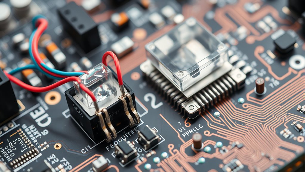
VCOs generate frequencies by using a control voltage to adjust their output, enabling precise and rapid frequency tuning.
This capability allows them to cover a wide range of frequencies, making them versatile for various applications.
With their ability to quickly shift frequencies, VCOs are essential in frequency hopping and data communication scenarios.
Voltage-Controlled Frequency Tuning
Adjusting the control voltage applied to a Voltage-Controlled Oscillator (VCO) generates output frequencies that can be finely tuned. The frequency tuning relies on the precise relationship between the control voltage and the VCO’s output. This capability is crucial for radio systems where frequency modulation is key.
In a Phase-Locked Loop (PLL), the VCO’s frequency is compared to a reference signal, and any phase error is corrected to guarantee synchronization and maintain signal integrity.
Here’s how it works:
- VCO and PLL Integration: The VCO provides the oscillating signal in a PLL.
- Control Voltage Impact: Directly affects the tuning range.
- Phase Error Correction: Guarantees synchronization in a PLL.
- Signal Integrity: High-quality VCOs minimize phase noise.
Wide Frequency Range Capabilities
Thanks to their design, VCOs can generate a wide range of frequencies by varying their output in response to changes in control voltage. This allows for precise frequency tuning, which is essential in applications like RF communication systems.
By manipulating the applied voltage, VCOs can cover several octaves, producing frequencies from a few MHz up to several GHz. The control system within the VCO guarantees this flexibility, offering a broad frequency generation spectrum.
The VCO’s output enhances synchronization and frequency multiplication when combined with a PLL. This synergy extends the range and optimizes the control system’s overall performance.
Rapid Frequency Adjustment
Building on VCOs’ wide frequency range capabilities, let’s explore how they achieve rapid frequency adjustment. VCOs generate frequencies by varying the control voltage, allowing for quick changes in output frequency. This ability is critical for communication systems where dynamic frequency modulation is essential.
The output frequency is directly proportional to the control voltage, enabling precise adjustments across a broad spectrum. High-quality VCOs maintain a stable frequency, even when the control voltage fluctuates, ensuring dependable performance.
Here’s why VCOs are indispensable:
- Speed: VCOs respond to control voltage changes in microseconds.
- Precision: Output frequency aligns accurately with control voltage variations.
- Versatility: Suited for a wide array of communication applications.
- Stability: Delivers reliable performance despite rapid frequency shifts.
Synchronization Role of PLLs
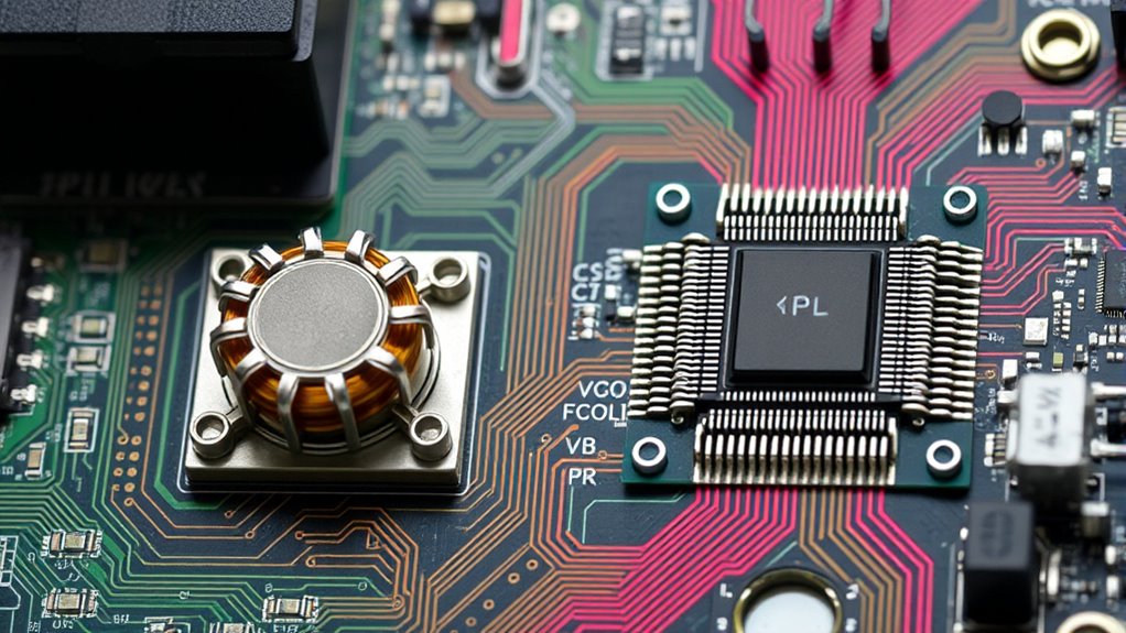
Although PLLs (Phase Locked Loops) might seem complex, they play an essential role in synchronizing output signals with reference inputs, guaranteeing frequency stability across various applications.
A PLL uses a phase detector to compare the input signal’s phase with the VCO (Voltage Controlled Oscillator). This comparison generates an error signal, critical for maintaining precise synchronization. A low-pass filter then smooths this error signal, stabilizing the control voltage applied to the VCO and enhancing the locking process.
In clock recovery applications, PLLs extract timing information from data streams, allowing you to synchronize clock signals accurately in high-speed digital systems.
This effective synchronization guarantees coherent demodulation and signal recovery, which is vital for improved performance in communication systems such as radio and telecommunications.
Applications of VCOs in Electronics
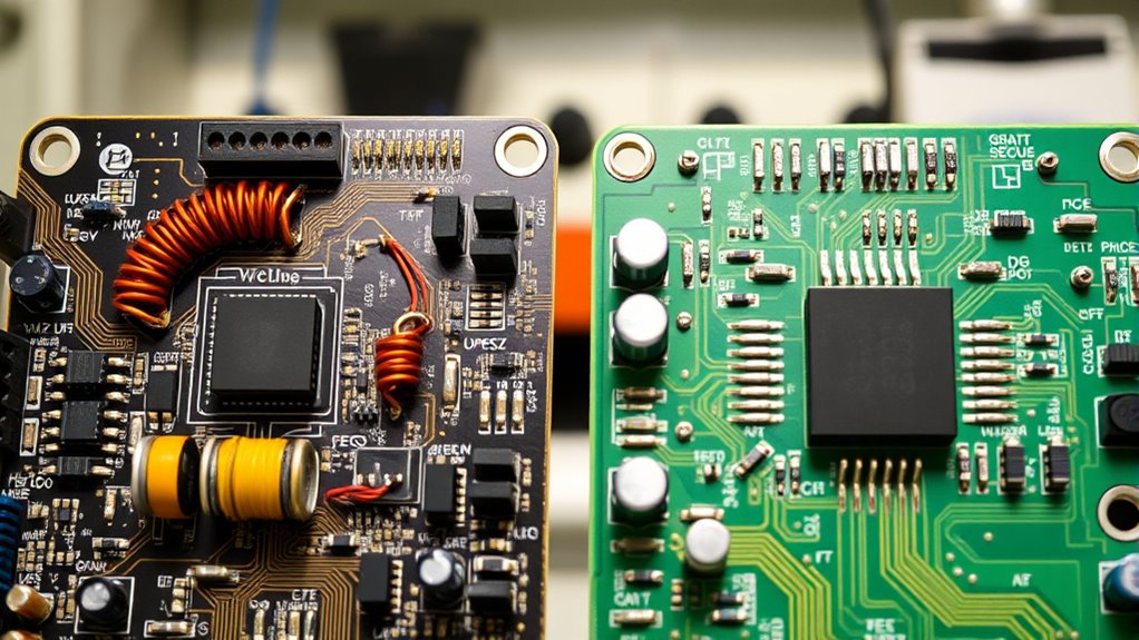
Understanding the synchronization role of PLLs highlights the significance of components like Voltage Controlled Oscillators (VCOs) in electronic systems.
VCOs are fundamental in several applications due to their ability to generate precise frequencies important for signal synchronization.
Here are four key applications of VCOs:
- Data Communication: VCOs guarantee reliable data transmission by enabling rapid frequency changes, which are critical for frequency hopping spread spectrum.
- Frequency Synthesizers facilitate the creation of multiple output frequencies from a single reference, which is essential for wireless communication and broadcasting.
- Integrated Circuits: VCOs provide high-frequency clock signals for digital systems like microprocessors and FPGAs.
- High-speed Data Acquisition: VCOs’ phase noise and tuning range impact stability and accuracy, which are important in processing applications.
Use Cases of PLLs in Communication Systems
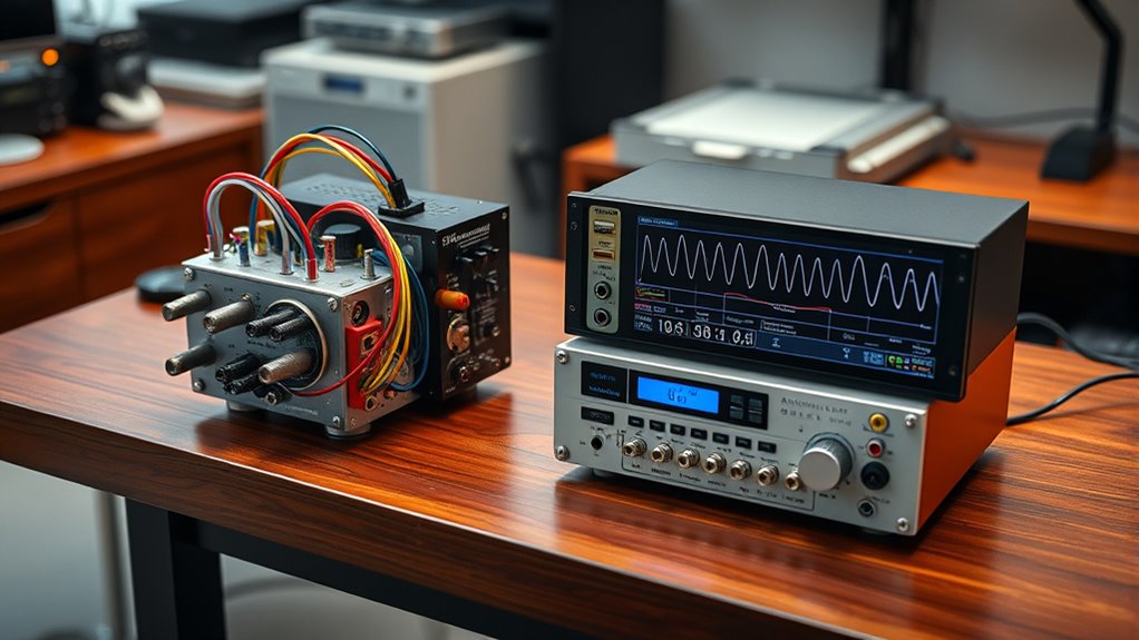
In communication systems, Phase-Locked Loops (PLLs) play an essential role by ensuring precise signal processing. They are vital for clock recovery, generating stable signals from data streams without timing references. In frequency modulation (FM) demodulation, they track the input signal’s frequency, effectively recovering modulated information. PLLs also generate local oscillator signals for up-conversion and down-conversion in digital wireless systems, enabling efficient signal processing and transmission. Their integration into a single IC reduces cellular handset size and cost, boosting mobile communication performance.
Here’s a quick overview:
| Use Case | Function | Benefit |
|---|---|---|
| Clock Recovery | Generates stable clock signals | Accurate data synchronization |
| FM Demodulation | Tracks the input signal frequency | Effective signal recovery |
| Local Oscillator Generation | Up/Down Conversion | Efficient wireless communication |
Differences in Frequency Stability
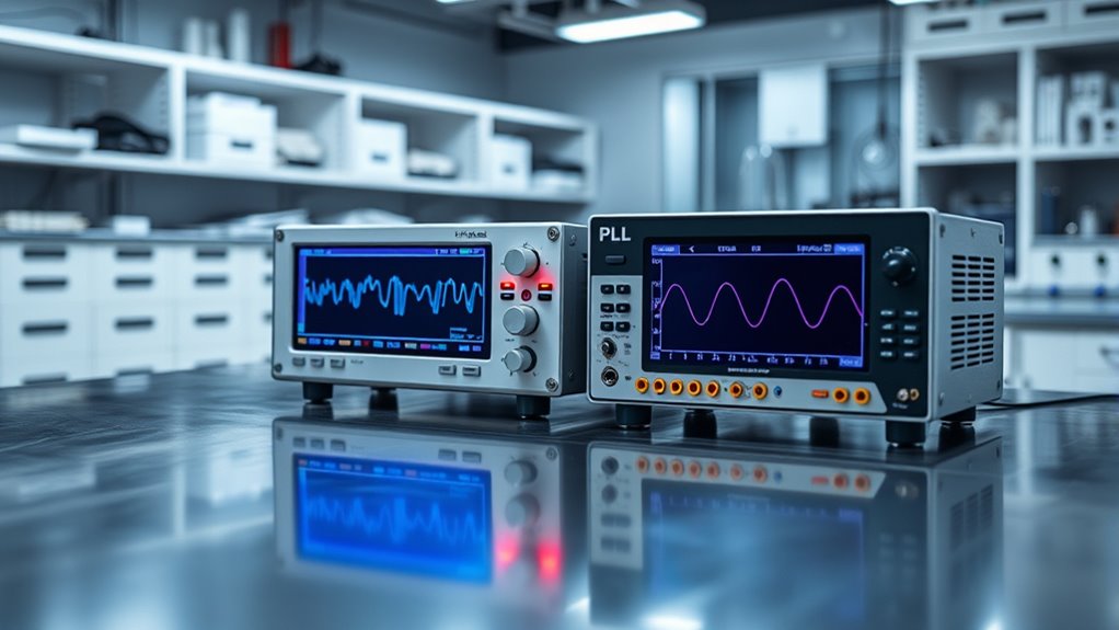
When considering frequency stability, you’ll notice that VCOs and PLLs handle it differently.
A VCO’s frequency can drift due to temperature changes, but a PLL uses a phase locking mechanism to maintain a stable output by continuously adjusting the frequency.
This makes PLLs more reliable in applications where tight frequency stability is essential.
Phase Locking Mechanism
Although VCOs and PLLs are essential in frequency generation, they differ markedly in frequency stability.
In a PLL, the phase detector plays a significant role by comparing the phase of a reference signal with the VCO output. This comparison generates an error signal critical for the feedback loop.
This loop continuously adjusts the VCO, ensuring frequency stability by minimizing phase differences. Here’s how a PLL enhances stability compared to a standalone VCO:
- Error Signal Correction: The error signal helps stabilize the VCO output.
- Feedback Loop Mechanism: Constantly adjusts the VCO to match the reference.
- Noise Reduction: A low-pass filter smooths the error signal.
- Adaptability: The loop bandwidth allows frequency changes to be tracked.
Frequency Drift Impact
While both Voltage-Controlled Oscillators (VCOs) and Phase-Locked Loops (PLLs) are essential for frequency generation, they differ greatly in handling frequency drift.
Due to temperature shifts and power supply changes, a VCO’s frequency can easily wander, leading to poor frequency stability.
However, a PLL excels in this area by locking the VCO output to a reference signal. The PLL’s feedback mechanism constantly adjusts the frequency, counteracting drift and maintaining stability. This process guarantees that even with external disturbances, the frequency remains steady.
Thanks to its ability to quickly correct deviations, a PLL system offers lower phase noise and superior frequency stability than a standalone VCO. This makes PLLs particularly valuable in high-frequency applications.
Stability in Applications
The stability of frequency generation plays an essential role in various applications, and understanding the differences between VCOs and PLLs is key. A Voltage-Controlled Oscillator (VCO) can suffer from frequency stability issues due to control voltage fluctuations and noise susceptibility.
In contrast, a Phase Locked Loop (PLL) enhances frequency stability by using a control loop to adjust the VCO, locking onto a reference signal and achieving superior noise immunity.
Here’s why PLLs are often preferred:
- Stable Output: PLLs maintain a consistent frequency by correcting phase discrepancies.
- Noise Immunity: Narrow loop bandwidths in PLLs improve resistance to noise.
- Precision: PLLs are ideal for applications like communication systems needing high precision.
- Adaptability: Control loops in PLLs adjust to environmental changes, ensuring reliability.
Comparing Performance Parameters of VCOs and PLLs
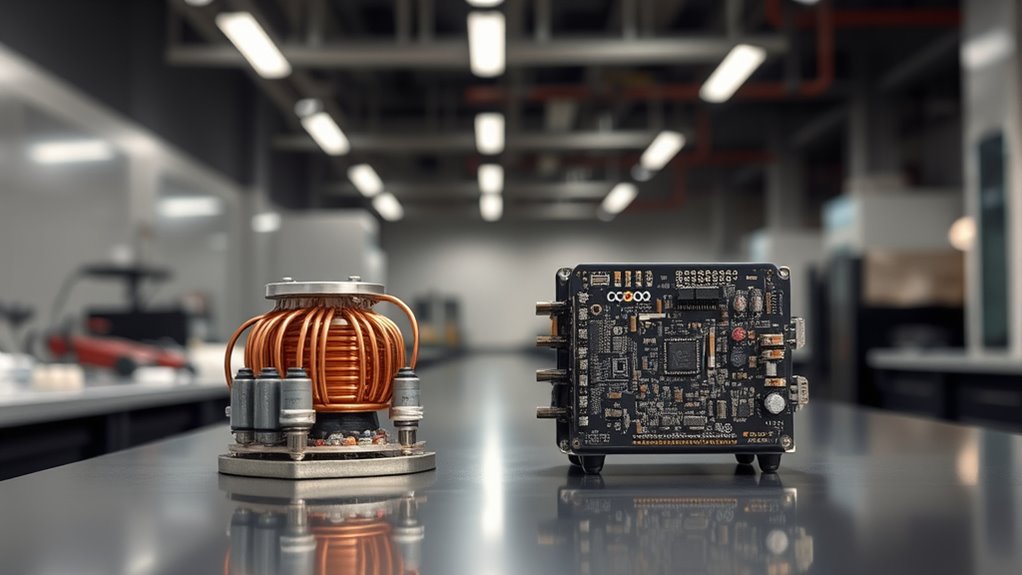
When comparing the performance parameters of VCOs and PLLs, it’s crucial to understand their distinct operational roles and advantages. A VCO generates frequencies based on input voltage, offering a broad frequency range but often suffering from higher phase noise as the range widens.
Meanwhile, a PLL combines a VCO with a phase detector and loop filter, ensuring frequency stability by locking onto a reference signal. This setup allows PLLs to mitigate phase noise better and maintain stable output frequencies despite input variations.
PLLs also excel in frequency synthesis, producing multiple precise output frequencies. They’ve specific metrics like lock-in range and pull-in time, which the loop filter design influences.
Consequently, for applications requiring precision and stability, PLLs are your go-to choice.
Conclusion
In understanding VCOs and PLLs, you’ve seen how each plays a unique role in electronics. VCOs offer quick frequency generation based on input voltage, making them essential for dynamic frequency adjustments. Meanwhile, PLLs maintain signal stability and precision by aligning output with a reference signal. While VCOs are indispensable for frequency generation, PLLs guarantee stability in communication systems. Each has its strengths, so choose based on your specific needs in signal processing.
FAQs
1. Which Is Better, a Direct Digital Synthesizer or a PLL?
You should choose between DDS and PLL based on your needs. If you require precise frequency changes quickly, go for DDS. If you need stable frequencies with low phase noise, choose a PLL. Consider your application’s specific requirements.
2. When to Use a PLL?
Use a PLL to synchronize signals, generate stable frequencies, or require precise frequency control. It’s ideal for clock recovery, frequency modulation, and minimizing phase noise in high-speed digital systems.
3. What Is the Difference Between PLL and FLL?
You’re looking at PLLs for phase synchronization and FLLs for frequency stability. Use PLLs when phase accuracy matters, like clock recovery. Choose FLLs for frequency consistency, especially in radio systems where phase isn’t essential.
4. What Is the Purpose of PLL?
You use a PLL to synchronize an output signal’s phase with a reference input, maintaining frequency stability. It’s essential for clock recovery, frequency synthesis, and coherent demodulation, simplifying frequency synthesizer design in various electronic applications.
