

Practical Applications of Op-Amps: Designing Electronic Circuits
Dive into the heart of signal amplification with a detailed exploration into Operational Amplifiers (Op-Amps) – an essential workhorse in electronics and circuit design! Discover how a small component can greatly impact sound systems, communication devices, and more. In this blog post, we’ll guide you through practical applications of Op-Amps, showing how they shape electronic circuits and define your everyday gadgets. Get ready to unlock memorable insights into the ever-evolving world of electronics!
Op-amps are widely used in various electronic applications, including amplifiers, oscillators, filters, comparators, voltage regulators, and instrumentation circuits. Additionally, op-amps can be used for tasks like voltage follower, summing amplifier, integrator/differentiator, and signal conditioning. Understanding the capabilities of op-amps can help you select the right type of op-amp for your application and ensure optimal performance.
Essential Aspects of Op-Amps in Circuit Design
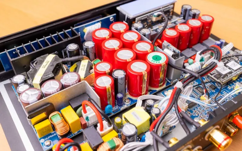
Understanding the essential aspects of operational amplifiers (op-amps) is crucial when designing electronic circuits. Op-amps are versatile devices that can play a pivotal role in various applications, such as amplification, filtering, and signal conditioning. Several key aspects must be considered to use op-amps in circuit design effectively.
One important factor is the open-loop gain of an op-amp. This refers to the gain the amplifier provides when no feedback is applied. The open-loop gain needs to be large enough to ensure accurate signal amplification. A high open-loop gain allows for better precision and linearity in the output signal.
Another aspect to consider is the input impedance of the op-amp. The input impedance refers to how much the op-amp affects the input signal source. Ideally, it should be significantly higher than the impedance of the signal source to avoid loading effects and maintain accurate signal representation. Using high-value resistors in op-amp circuits can help achieve this.
Furthermore, understanding the impact of negative feedback on op-amp behavior is crucial in circuit design. Negative feedback is a technique that stabilizes and improves the performance of op-amps by feeding a portion of the output signal back to its input with appropriate polarity. Employing negative feedback helps reduce distortion, increase stability, and improve linearity in amplification circuits.
It’s also important to consider power supply effects in circuit design. Power supply noise and signal ripple can introduce unwanted disturbances into op-amp operation. Connecting bypass capacitors across each power supply pin and ground can help mitigate these effects, providing the op-amp with cleaner and more stable power.
Additionally, practical op-amps have non-ideal features such as finite input impedance and non-zero output impedance. Understanding these characteristics allows designers to minimize undesired effects and optimize circuit performance. By incorporating techniques like buffering or impedance matching, designers can mitigate issues related to non-ideal op-amp behavior.
Overall, comprehending the essential aspects of op-amps in circuit design involves considering factors such as open-loop gain, input impedance, negative feedback, power supply effects, and addressing non-ideal features. By carefully evaluating these aspects and applying suitable design techniques, one can harness the full potential of op-amps in their electronic circuits.
Impact of Finite Input and Output Impedances
In op-amp applications, finite input and output impedances play a significant role. Input impedance refers to the resistance presented by the input terminals of an op-amp to the signal source. In contrast, output impedance represents the resistance exhibited by the amplifier’s output terminals to the load it drives.
The finite input impedance of an op-amp affects its ability to effectively accept signals from various sources without altering their characteristics. The input impedance should be high since this allows minimal current flow into the amplifier, reducing potential loading effects on the signal source. High-value resistors are commonly used in op-amp circuits to achieve elevated input impedance.
On the other hand, output impedance impacts how well an op-amp can drive a load without significant signal degradation. A low output impedance ensures minimal voltage drop across the amplifier’s output terminals when connected to a load. If the output impedance is too high, it can reduce signal integrity and inaccurate voltage levels at the load.
Understanding and addressing these finite input and output impedances are crucial for optimal performance in op-amp circuits. By carefully selecting component values and employing techniques such as buffering or impedance matching, designers can mitigate loading effects on the signal source and ensure accurate transmission of signals to loads.
For example, imagine designing an audio amplifier circuit where an op-amp is used to amplify the audio signal. If the input impedance of the op-amp is too low, it will draw significant current from the audio source, causing distortion and loss of signal quality. However, by selecting an op-amp with high input impedance or using appropriate resistors in the circuit, one can avoid these issues and achieve faithful amplification.
By considering both the finite input and output impedances of an op-amp, designers can maximize the fidelity and efficiency of their circuits while minimizing potential signal degradation or loading effects.
- In op-amp applications, it is important to consider both the finite input and output impedances. High input impedance is desirable to minimize current flow from the signal source, while low output impedance ensures minimal voltage drop across the amplifier’s outputs when connected to a load. By selecting appropriate component values and using techniques such as buffering or impedance matching, designers can mitigate loading effects on the signal source and ensure accurate transmission of signals to loads, ultimately maximizing circuit fidelity and efficiency.
Dealing with Non-Ideal Features and Errors
While operational amplifiers (op-amps) are widely used in electronic circuits, they are imperfect components with non-ideal features and errors. Understanding and mitigating these aspects is crucial for designing reliable and accurate circuits.
One non-ideal feature of op-amps is their finite input impedance. This means they draw a small amount of current from the signal source when connected, which can affect the voltage across the source. To minimize this impact, choosing an op-amp with a sufficiently high input impedance compared to the source impedance is important. By doing so, we can ensure minimal distortion in the circuit.
For instance, imagine designing a sensor interface circuit with an op-amp with low input impedance. If the sensor has a high output impedance, it could lead to significant errors in the measurement due to the voltage drop across the source impedance caused by the op-amp’s input current draw. However, we can mitigate this issue by selecting an op-amp with high input impedance and obtaining accurate measurements.
Another non-ideal feature is the finite gain of op-amps. Ideally, op-amps have very high open-loop voltage gain. However, practical limitations result in finite gains that can vary with frequency or temperature. This can introduce errors in amplification and affect circuit performance. Compensating for these variations may require careful design considerations, such as using feedback networks or compensating capacitors to maintain stability over different operating conditions.
Additionally, op-amps have input bias currents and input offset voltages that contribute to errors in circuit operation. Input bias currents flow into or out of the inputs, creating voltage drops across source resistances that can disturb signal accuracy. Input offset voltages introduce DC offsets that can lead to incorrect signal processing or biased outputs.
To deal with these non-ideal features and errors, designers employ various techniques. These include using matched resistors to minimize input bias currents, offset-nulling techniques to mitigate offset voltages, and implementing temperature compensation methods. By carefully selecting components and configuring the feedback network, designers can minimize these errors and optimize circuit performance.
With an understanding of how to manage non-ideal features and errors in op-amps, let’s explore the practical applications of op-amps in electronic circuits.
Practical Application of Op-Amps in Circuits

Op-amps are versatile components that find numerous applications in electronic circuits due to their ability to amplify signals, perform mathematical operations, and maintain stability within certain input ranges. Let’s dive into some practical uses of op-amps:
- Amplification: One common application of op-amps is amplifying weak input signals to a desired output level. This is particularly useful in audio amplifiers, where op-amps boost low-level audio signals from sources like microphones or musical instruments before driving speakers.
- Signal Conditioning: Op-amps can be employed for signal conditioning, such as filtering, rectifying, or smoothing signals. For example, in sensor interface circuits, op-amps can amplify and filter signals from temperature or pressure sensors before further processing.
- Comparator: Op-amps can determine whether one signal is greater than or equal to another. This makes them suitable for applications like overvoltage protection or detecting threshold levels in various systems.
- Voltage Reference: Op-amps with stable output voltages can be voltage references in electronic circuits. To ensure accuracy, they provide a precise, constant voltage that other components can reference.
- Oscillators: By incorporating feedback networks with appropriate frequency-selective components, op-amps can generate oscillating waveforms for generating clocks, timekeeping systems, or creating frequencies for various applications.
- Active Filters: Op-amps can be utilized to construct active filters, where their high input impedance and low output impedance enable precise shaping of frequency response curves. This is particularly beneficial in applications like audio equalizers or data signal filtering.
Remember, these are just a few examples of op-amps’ diverse applications in electronic circuit design. The possibilities are vast, and with creativity and innovation, op-amps can be tailored to suit specific circuit requirements.
Distinct Uses of Different Op-Amp Types
Operational amplifiers (op-amps) come in various types, each with unique characteristics that make them suitable for different applications. Understanding these distinctions can help engineers design electronic circuits more effectively. Let’s explore the distinct uses of different op-amp types:
One commonly used type is the inverting op-amp. As its name suggests, it produces an inverted output compared to its input. This configuration is useful for applications like signal amplification and wave shaping. For instance, if you have a low-amplitude signal that needs to be amplified, you can use an inverting op-amp to achieve the desired gain.
Imagine you need to amplify a small audio signal from a microphone to drive a speaker. An inverting op-amp circuit with appropriate feedback resistors can increase the amplitude of the signal without sacrificing audio fidelity.
Another widely utilized op-amp configuration is the non-inverting op-amp, which maintains the same polarity between input and output signals. This type is often employed when a higher input impedance is required or buffering signals from voltage dividers or sensors.
For instance, consider a scenario where you want to measure the voltage across a temperature sensor while minimizing any loading effects on the sensor. You can buffer the signal by employing a non-inverting op-amp circuit with high input impedance and avoid altering the original reading.
Additionally, certain specialized op-amp configurations are tailored for specific purposes. A summing amplifier allows multiple inputs to be combined into one output by summing their voltages with different weights assigned by resistors. A voltage follower has a unity gain (gain value of 1) and replicates its input exactly at the output, serving as an isolation barrier between two circuits with differing voltage requirements.
Engineers can select and configure the appropriate op-amp to optimize their circuit designs for specific applications by understanding these distinct uses of different op-amp types.
Now that we have explored the various uses of different op-amp types, let’s focus on another critical aspect of designing electronic circuits: mitigating power supply effects in op-amps.
Mitigating Power Supply Effects in Op-Amps

Op-amps are highly sensitive to variations and disturbances in their power supply. These fluctuations can adversely affect their performance and introduce noise and errors into circuit operations. However, there are ways to mitigate power supply effects and ensure reliable functionality. Let’s delve into some techniques:
Power supply noise often arises from various sources, such as switching regulators or other components sharing the same power source. To counteract this, bypass capacitors can be connected across each power supply pin of the op-amp and grounded. These capacitors act as reservoirs, supplying clean and stable power to the op-amp by reducing high-frequency noise.
Consider a scenario where an op-amp circuit is connected to a DC motor controller that generates significant switching noise. By strategically placing bypass capacitors near the power supply pins of the op-amp with appropriate capacitance values, the noise introduced by the motor controller can be significantly reduced, leading to improved signal integrity.
Power signal ripple – caused by components with time-varying currents drawing power from the same supply lines – can also impact op-amp behavior. Like bypass capacitors, appropriately sized capacitors can help smooth out these voltage variations and minimize ripple effects.
It’s important to mention that while capacitors can mitigate certain power supply effects, they must be chosen carefully based on factors such as frequency response requirements and current consumption. The size and type of capacitors used should match the specific needs of the circuit design.
Engineers can improve op-amp circuits’ stability, reliability, and performance by employing these techniques to mitigate power supply effects, ensuring accurate operation in various applications.
Advance Usage: Drawing Current into Op-Amps
One of the lesser-known but highly beneficial applications of operational amplifiers (op-amps) is their ability to draw current into the circuit. While op-amps are generally considered devices that amplify signals and provide voltage gain, they can also draw current from an external source, allowing for enhanced functionality in various electronic circuits.
When an op-amp inputs current from an external source, it can serve as an active element in a circuit, performing tasks beyond traditional amplification. This technique is particularly useful when there is a need for additional current or when driving a specific load requires more power than what the op-amp alone can provide.
For example, consider a scenario where a circuit requires a higher output current than what the op-amp can directly deliver. By connecting the load to the op-amp output and utilizing external current sources, such as transistors or other devices, the op-amp can draw additional current to drive the load effectively. This configuration enables the op-amp to function as a more powerful driver, overcoming limitations that may arise due to its internal design constraints.
Imagine you are designing an audio amplifier circuit that needs to deliver high-quality sound through speakers. In this case, you may choose an op-amp with excellent voltage characteristics but limited capability to supply significant amounts of current. By drawing additional current into the op-amp from external sources, you ensure that your audio amplifier has sufficient power to drive the speakers effectively and produce optimal audio performance.
It’s important to note that drawing additional current into an op-amp does come with some considerations. First and foremost, careful attention should be given to ensure stability and prevent oscillations or other unintended effects. Adding external components like feedback resistors and capacitors can help maintain stability while drawing current into the op-amp.
Additionally, it is crucial to select suitable external current sources based on the requirements of the circuit. These sources should be capable of providing the necessary current without compromising the op-amp’s performance or exceeding its maximum ratings.
In summary, drawing current into an operational amplifier offers advanced usage that expands the capabilities of these versatile components. By utilizing external current sources, op-amps can deliver higher output currents, drive challenging loads, and enhance the overall functionality of electronic circuits. However, careful consideration must be given to stability and component selection to ensure optimal performance.
