

What is Slew Rate in Op Amp? A Comprehensive Guide
In electronics, operational amplifiers (op amps) are fundamental components indispensable in various applications, from audio amplifiers to signal processing circuits. One critical parameter that engineers often encounter when dealing with op amps is the “slew rate.” Understanding the slew rate is crucial for designing circuits with optimal performance and reliability.
What is Slew Rate in Op Amp?
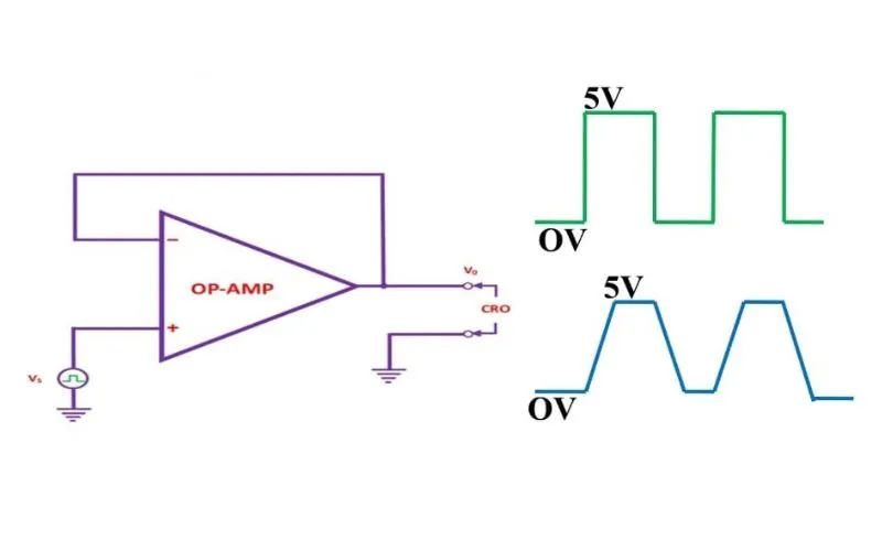
Slew rate refers to the rate of change of the output voltage concerning time. In simpler terms, it measures how fast an op amp can respond to changes in the input signal. Typically, this is specified in volts per microsecond (V/µs). Understanding slew rate is essential, especially in applications where the input signal undergoes rapid changes or transitions.
The Significance of Slew Rate
The slew rate is a critical parameter for several reasons:
- Signal Fidelity: In applications where the input signal contains high-frequency components, such as audio amplifiers or data acquisition systems, maintaining signal fidelity is crucial. A high slew rate ensures the op amp can accurately reproduce rapid signal changes without distortion.
- Transient Response: Op amps with a higher slew rate exhibit better transient response characteristics. This means they can quickly settle to a stable output voltage after a change in the input signal, minimizing overshoot and undershoot.
- Frequency Response: Slew rate directly affects the frequency response of the op amp. Higher slew rates enable op amps to handle higher-frequency signals effectively, expanding their usability in a broader range of applications.
Factors Affecting Slew Rate
Slew rate, a crucial parameter in op amp performance, is influenced by various factors, each playing a significant role in determining the amplifier’s ability to respond to rapid changes in input signals. Engineers must understand these factors to design circuits with optimal performance characteristics.
Internal Circuitry
The internal circuit design of an operational amplifier has a substantial impact on its slew rate. Op amps with advanced architectures, such as those employing high-speed transistors and sophisticated compensation techniques, tend to exhibit higher slew rates. These op amps are engineered to minimize internal capacitances and propagation delays, enabling faster response times to input signal variations.
Moreover, the topology of the input and output stages and the compensation scheme employed can affect the amplifier’s ability to slew quickly. For instance, op amps designed with cascade or current feedback configurations may offer superior slew rate performance compared to traditional voltage feedback designs.
Power Supply Voltage
The power supply voltage directly influences the slew rate of an op amp. As the supply voltage increases, the available headroom for signal swing expands, allowing for faster output transitions. This is because a higher voltage enables the op amp’s output stage to drive larger currents, facilitating quicker charging and discharging of capacitive loads.
Engineers often select op amps with adequate power supply voltage ratings to ensure a sufficient slew rate for their application requirements. However, striking a balance is essential, as excessively high supply voltages can increase power consumption and thermal considerations.
Load Capacitance
The capacitive load connected to the op-amp output can significantly impact its slew rate. Capacitive loads introduce additional charging and discharging currents, which the op amp’s output stage must supply. As the capacitance increases, the time required to slew the output voltage increases, resulting in a lower slew rate.
Engineers must carefully consider the capacitive loading conditions in their circuit designs to ensure that the op amp can meet the required slew rate specifications. Techniques such as using buffer amplifiers or minimizing the capacitive loading through appropriate circuit layout and component selection can help mitigate the effects of load capacitance on slew rate.
Temperature and Process Variations
Temperature and process variations can affect the slew rate of an op amp, particularly in integrated circuit implementations. Variations in operating temperature can impact the speed of transistor devices and introduce changes in device characteristics, leading to variations in slew rate.
Similarly, process variations during semiconductor fabrication can result in differences in device parameters, such as transistor gain and capacitances, affecting the slew rate. Manufacturers often provide slew rate specifications over specified temperature ranges and process variations to account for these effects.
Calculating Slew Rate
The slew rate of an op-amp can be calculated using the following formula:
Slew Rate = ΔtΔVout
Where:
- is vthe change in output voltage.
- Δt is the corresponding change in time.
Conclusion
FAQs
What are the implications of a low slew rate in op amps?
A low slew rate can lead to signal distortion and inadequate response to rapid changes in input signals. This can result in signal clipping, where the op amp fails to accurately reproduce the input waveform, leading to distorted output signals. A low slew rate can significantly degrade performance and compromise system functionality in applications requiring high-frequency signal processing or precise transient response.
How does the slew rate affect amplifier stability?
The slew rate is closely linked to amplifier stability, particularly in feedback systems. An inadequate slew rate can cause slew-induced distortion and instability, leading to oscillations and ringing in the output signal. This instability can degrade system performance and may even lead to circuit failure in extreme cases. Proper consideration of slew rate is essential for maintaining stability and ensuring reliable operation of amplifier circuits.
