
Transformer Principle – How It Works and Applications
When you explore the transformer principle, you’ll see electromagnetic induction, where alternating magnetic flux induces a voltage across coils. By manipulating the winding turns ratio between primary and secondary coils, you can effectively control voltage levels with minimal power loss. This principle is essential for ensuring efficient energy transfer in electrical systems. Are you curious how the induced voltage and magnetic flux rate affect performance? Let’s explore each aspect, starting with the basic construction and types of transformers.
Key Takeaways
- Transformers operate on the principle of electromagnetic induction to transfer energy between two circuits.
- Faraday’Faraday’sinduction governs the induction of alternating magnetic flux in transformers.
- The turns ratio between primary and secondary windings determines the voltage transformation.
- Efficient energy transfer relies on minimizing copper and iron losses in the transformer.
- The EMF equation relates induced voltage to the number of turns and the rate of magnetic flux change.
What Is a Transformer?

A transformer is a static electrical device that transfers electrical energy between circuits using electromagnetic induction. When the primary winding is connected to an alternating current power source, it creates a magnetic field in the core, which is usually made of silicon steel. This magnetic field induces a voltage in the secondary winding through mutual induction.
The transfortransformer’s winding is where the input voltage is applied, and the secondary winding is where you get the output voltage. Thanks to Faraday’Faraday’se changing magnetic field in the core induces an electromotive force (EMF) in the secondary winding. This principle allows the transformer to either increase (step-up) or decrease (step-down) voltage levels without changing the frequency of the alternating current power.
Understanding the core is crucial because it efficiently channels the magnetic flux generated by the windings, minimizing energy loss and maximizing efficiency.
Transformers are essential in power generation and distribution. They ensure that voltage levels are appropriate for various applications, from industrial machinery to household appliances. They help maintain a stable and efficient electrical supply, making modern electrical systems possible.
Types of Transformers
Understanding the various types of transformers helps you choose the right one for your specific application. The transformer types are determined by their core material, winding arrangement, and intended usage. Each type utilizes mutual induction to transfer electrical energy between circuits.
Step-up transformers increase voltage levels, making them ideal for long-distance transmission of electricity. On the other hand, step-down transformers decrease voltage, which is essential for powering low-voltage devices in homes and businesses. Auto-winding transformers feature a single winding over a laminated core, offering a simpler design and cost efficiency for certain applications.
Here’s aHere’s overview of some common transformer types:
- Power transformers: Used in high-voltage transmission networks to transfer electricity efficiently over long distances.
- Distribution transformers: Step down the voltage for local distribution to residential and commercial users.
- Measurement transformers: Provide accurate voltage and current measurements for metering and protection purposes.
Each type of transformer is optimized for its specific role, leveraging different core materials and winding arrangements to meet various electrical demands.
Transformer Construction
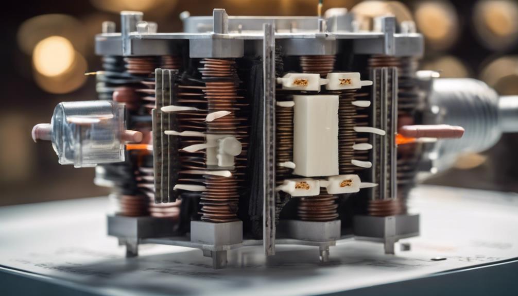
In transformer construction, you’ll fyou’llimary and secondary windings intricately linked by a magnetic core crafted from laminated silicon steel. The primary winding connects to the AC power supply, creating a magnetic field in the core. This magnetic flux, governed by Faraday’Faraday’sinduction, transfers energy to the secondary winding, which then supplies power to the load. The core material, laminated silicon steel, minimizes eddy current losses while enhancing magnetic properties, ensuring efficient energy transfer.
| Component | Function | Material |
|---|---|---|
| Primary Winding | Induces magnetic field | Copper/Aluminum wire |
| Secondary Winding | Generates induced voltage | Copper/Aluminum wire |
| Transformer Core | Links windings magnetically | Laminated silicon steel |
The construction follows the principle of mutual induction, where the magnetic flux generated by the primary winding induces a voltage in the secondary winding. Laminated silicon steel is used for the core to reduce eddy current losses, thereby improving efficiency. These laminations are pivotal as they break the path of eddy currents, reducing heat and energy loss. This structure ensures that the magnetic properties of the core are optimized for efficient energy transfer between windings, making the transformer a highly effective device in electrical systems.
Working Principle
Building on the transfortransformer’sction, you’ll syou’ll Faraday’Faraday’smutual induction powers its working principle. When the AC supply is connected to the transformer primary winding, it creates an alternating magnetic flux in the core. This changing magnetic field is essential for mutual induction between the primary and secondary windings.
Key points to understand the working principle include:
- Faraday’Faraday’sinduction: The alternating magnetic flux induces an emf in the secondary winding.
- Turns ratio: The secondary voltage is determined by the ratio of the number of turns in the primary and secondary windings.
- Electromagnetic induction: The direction of the induced emf in the secondary winding is opposite to the applied voltage in the primary winding.
As the alternating current flows through the primary winding, the alternating magnetic flux generated in the core induces an emf in the secondary winding. This induced emf is directly proportional to the turns ratio of the windings.
If the secondary winding has more turns than the primary, the secondary voltage will be higher, and vice versa. This is how the transformer efficiently transfers electrical energy from the primary side to the secondary side using the principle of electromagnetic induction.
EMF Equation
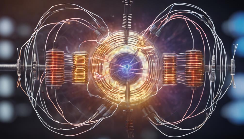
You can derive the EMF equation of a transformer by considering the relationship between the number of turns in the coils, the magnetic flux, and the time period. The induced voltage (EMF) in the primary coil is directly proportional to the rate of change of magnetic flux and the number of turns in the coil. Mathematically, this is expressed as ( E_1 = N_1 rac{dphi}{dt} ), where ( E_1 ) is the induced voltage in the primary coil, ( N_1 ) is the number of turns in the primary coil, and ( rac{dphi}{dt} ) represents the rate of change of magnetic flux over the time period.
Similarly, for the secondary coil, the induced voltage ( E_2 ) is given by ( E_2 = N_2 rac{dphi}{dt} ), where ( N_2 ) is the number of turns in the secondary coil. By comparing these equations, you can determine the voltage output of the transformer: ( rac{E_2}{E_1} = rac{N_2}{N_1} ). This ratio shows how the number of turns influences the voltage transformation.
The EMF equation is essential for calculating the effective voltage output and understanding how efficiently the transformer operates. By mastering this equation, you can predict the transfortransformer’sance and design it to meet specific requirements in electrical systems.
Transformer Efficiency
To boost transformer efficiency, you need to focus on minimizing power losses and managing loads effectively. Reducing copper and iron losses plays a significant role in achieving higher efficiency.
Additionally, balancing the load guarantees the transformer operates at its peak performance, reducing energy waste.
Power Loss Minimization
Maximizing transformer efficiency hinges on minimizing copper and iron losses during operation. Efficiency is key to reducing power loss during voltage transformation.
Copper losses stem from circulating currents in the windings, while iron losses, known as hysteresis, occur because magnetic molecules lag within the core material. Minimizing power loss in these areas is essential for achieving high transformer efficiency.
To boost transformer efficiency, you should focus on:
- Reducing copper losses: This involves using materials with lower resistance for windings, which minimizes circulating currents.
- Mitigating iron losses: Opt for high-quality core materials with low hysteresis to reduce energy lost in the magnetic cycle.
- Increasing voltage: By stepping up the voltage, you can reduce the current, which in turn lowers both copper and iron losses.
In real-world applications, transformer efficiency typically ranges between 94% and 98%. This high efficiency is achieved by carefully managing copper and iron losses. Focusing on these factors greatly improves your transformer’s overall performance rates more effectively with minimal power loss.
Optimal Load Management
Ensuring efficient load management is pivotal for maintaining high transformer efficiency and minimizing energy wastage. By optimizing load management, you can markedly reduce power losses and achieve substantial cost savings. It’s vitIt’so understand that efficiency is the ratio of output power to input power. Modern transformers are designed to achieve efficiencies above 95%, which helps in energy conservation and enhances overall performance.
When you manage the load correctly, your transformers operate at their peak efficiency levels. This reduces unnecessary energy consumption and prolongs the lifespanequipment’s lifespan. Efficient load management ensures that the input power is effectively converted to output power without excessive losses.
Here’s aHere’s look at the benefits of ideal load management:
| Benefit | Emotional Impact |
|---|---|
| Cost Savings | More financial resources freed up |
| Energy Conservation | Contribute to a greener planet |
| Enhanced Performance | Reliable and consistent power supply |
Conclusion
You’ve nYou’ve a solid grasp of the transformer principle. By understanding the relationship between magnetic flux, winding turns, and induced voltage, you can confidently predict transformer performance.
Whether you’re dyou’re with step-up or step-down transformers, the core concepts remain the same. Efficient energy transfer and voltage transformation are at your fingertips, minimizing power losses and optimizing electrical systems.
Keep this knowledge handy for all your future electrical endeavors!
FAQs
What is the basic principle of a transformer?
A transformer operates on the principle of electromagnetic induction, which states that a changing magnetic field in a coil of wire induces a voltage across another coil placed nearby. In simple terms:
- AC Voltage Applied: When an alternating current (AC) voltage is applied to the primary winding of the transformer, it creates a varying magnetic field in the transfortransformer’sagnetic Field: This varying magnetic field induces a voltage in the secondary winding of the transformer.
- Voltage Transformation: The voltage induced in the secondary winding can be higher or lower than the primary voltage, depending on the windings’ windings’ turns ratio. This allows the transformer to step up (increase) or step down (decrease) the voltage.
How does a transformer work?
A transformer works through the following key components and steps:
- Primary Winding: The primary winding is connected to the input AC voltage source. When AC voltage is applied, it creates an alternating magnetic flux in the transfortransformer’sagnetic Core: The magnetic core, typically made of laminated iron, guides the magnetic flux and minimizes energy losses.
- Secondary Winding: The magnetic flux induces an alternating voltage in the secondary winding. The amount of induced voltage depends on the number of turns in the secondary winding relative to the primary winding.
- Turns Ratio: The ratio of the number of turns in the primary winding to the number of turns in the secondary winding determines whether the transformer steps up or down the voltage.
- Step-Up Transformer: More turns in the secondary winding than the primary winding increase the voltage.
- Step-Down Transformer: Fewer turns in the secondary winding than the primary winding decrease the voltage.
What are the different types of transformers based on their function?
Transformers are classified into various types based on their function, including:
- Step-up Transformers increase the voltage from the primary winding to the secondary winding. They are commonly used in power generation stations to transmit electricity over long distances.
- Step-Down Transformer: This transformer decreases the voltage from the primary winding to the secondary winding. It is used in distribution networks to reduce the voltage to a safer, usable level for homes and businesses.
- Isolation Transformer: This transformer provides electrical isolation between the primary and secondary circuits without changing the voltage level. It is used for safety and noise reduction in sensitive equipment.
- Autotransformer: Uses a single winding that acts as primary and secondary. It can step up or down the voltage with a smaller, more compact design.
- Current Transformer (CT): Measures alternating current (AC) by producing a reduced current proportional to the current in the primary winding. They are used in electrical metering and protection.
- Potential Transformer (PT): Measures high voltage by producing a reduced voltage proportional to the voltage in the primary winding. They are used in high-voltage measurement systems.
What is the importance of the turn ratio in a transformer?
The turns ratio is crucial in determining how a transformer modifies the voltage:
- Turns Ratio Formula: The turns ratio is the ratio of the number of turns in the primary winding (NpN_p) to the number of turns in the secondary winding (NsN_s). Turns Ratio=NpNstext{Turns Ratio} = frac{N_p}{N_s}
- Voltage Relationship: The voltage induced in the secondary winding (VsV_s) is related to the primary voltage (VpV_p) by the turns ratio: VsVp=NsNpfrac{V_s}{V_p} = frac{N_s}{N_p}
- Step-Up or Step-Down: If Ns>NpN_s > N_p, the transformer steps up the voltage; if Ns<NpN_s < N_p, it steps down the voltage.
What are some practical applications of transformers?
Transformers are essential components in various applications, including:
- Power Distribution: Step-down transformers reduce the high voltage from power lines to a lower voltage suitable for use in homes and businesses.
- Power Generation: Step-up transformers increase the voltage generated by power plants for efficient transmission over long distances.
- Electronics: Isolation transformers provide electrical isolation in sensitive electronic devices to protect against electrical shocks and reduce noise.
- Industrial Equipment: Transformers match the voltage to the required operating levels in machinery and industrial equipment in machinery and industrial equipment.
- Renewable Energy: Transformers play a key role in solar and wind energy systems by converting the generated power to a usable voltage level for the grid.
How does a transformer ensure efficient power transfer?
A transformer ensures efficient power transfer by:
- Minimizing Losses: The laminated iron core reduces eddy currents, while high-quality winding materials reduce resistive losses.
- Magnetic Coupling: The close magnetic coupling between the primary and secondary windings ensures that most of the magnetic flux generated by the primary winding is transferred to the secondary winding.
- Load Matching: Transformers are designed to match the load impedance with the source impedance, maximizing power transfer and minimizing energy loss.
What are some common issues that can affect transformer performance?
Common issues that can affect transformer performance include:
- Overheating: Caused by overloading or poor ventilation, leading to insulation breakdown and reduced efficiency.
- Core Saturation Occurs when the magnetic core cannot handle the magnetic flux, leading to distortion in the output voltage.
- Winding Short Circuits: This can occur due to insulation failure, causing overheating and potential transformer failure.
- Humming Noise: Often caused by loose laminations in the core or mechanical vibrations, which can be annoying but are usually not harmful.
- Eddy Currents: Induced currents in the core that cause energy losses are minimized by using laminated cores.
Understanding the basic principles and components of transformers, as well as their various applications and potential issues, can help you better appreciate their role in modern electrical systems.
