

Mysteries of Sequence Impedance in Power System Elements
Each element of the power system will present an impedance to different phase sequence components of current, which may not be similar. For instance, the impedance that any part of the equipment offers to the positive sequence current will not be the same as that of the negative or zero sequence current. Therefore, in unsymmetrical fault calculations, each part of the equipment will have three values of Impedance, one corresponding to each sequence current viz.
-
Positive sequence impedance (Z1)
-
Negative sequence impedance (Z2)
-
Zero sequence impedance (Z0)
The Impedance offered by a circuit or equipment to positive-sequence current is said to be positive-sequence Impedance, and Z1 represents it. Likewise, impedances presented in any course or equipment to negative-sequence and zero-sequence currents are named negative sequence impedance (Z2) and zero sequence impedance (Z0).
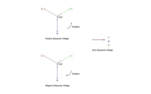
Key Points
The following points may be noted:
- In a 3-phase balanced system, each portion of the equipment or circuit offers only one Impedance: the one provided to positive sequence or normal sequence current. This is anticipated because negative and zero arrangements exist in the 3-phase balanced system.
- In a 3-phase unbalanced system, each part of the equipment or circuit will have three impedance values: positive sequence, negative sequence impedance, and zero sequence impedances.
- The positive and negative sequence impedances of linear, symmetrical, and static circuits. (e.g., transmission lines, cables, transformers, and fixed loads) are identical to those used in the analysis of balanced conditions. This is because the Impedance of such circuits is independent of the phase order, provided the voltages applied are proportional. The positive and negative sequence impedances of rotating machines (e.g., synchronous and induction motors) are normally different.
- The zero sequence impedance depends upon the path the zero sequence current takes. This path normally differs from the path taken by the positive and negative sequence currents, so the zero sequence impedance usually differs from the positive or negative sequence impedance.
Sequence Impedance of Power System Elements
The design of impedances in various elements of the power systems (e.g., Generators, Transformers, Transmission lines, etc.) to positive sequence, negative sequence, and zero sequence currents are of considerable importance in determining the fault current in a 3-phase unbalanced system. This post does not cover a real concern about this topic, but short preliminary explanations may be of interest here.
The following are the three main parts of equipment that will be considered for the Sequence Impedance of Power System Elements.
-
Synchronous Generators
-
Transformers
-
Transmission lines
Synchronous Generators
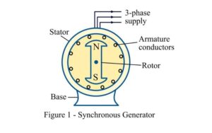
These rotating machines‘ positive, negative, and zero sequence impedances differ. The positive sequence impedance of a synchronous generator is equal to the synchronous Impedance of the device. The zero-sequence Impedance is much less than the positive-sequence Impedance. The zero sequence impedance is a variable item, and if its value is not given, it may be assumed to be equal to the positive sequence impedance. In simple:
Negative-sequence impedance < Positive-sequence impedance
Zero-sequence Impedance = variable item = may be taken equal to positive-sequence impedances if its value is not given.
It might be advisable to mention here that any impedance Ze in the earth connection of star-connected systems has the effect of introducing an impedance of 3 – Ze per phase. The three equal zero-sequence currents in phase do not sum to zero at the start point but flow back along the neutral connection.
Transformers
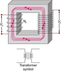
Since the transformers have the same Impedance with reversed phase rotation, their positive-sequence and negative-sequence impedances are equal. This value is similar to the Impedance of the transformer. However, the zero-sequence impedance depends upon the earth connection. If there is a through-the-circuit for earth current, the zero-sequence Impedance will equal the positive-sequence Impedance, or it will be infinite.
Positive-sequence impedance
= Negative-sequence impedance
= Impedance of transformers
Zero-Sequence impedance
= positive-sequence impedance, in case there is a circuit for earth current
= Infinite, if there is no through-the circuit for earth current.
Transmission Lines
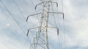
A line’s positive-sequence and Negative-sequence impedances are the same, this value being equal to the normal Impedance of the line. This is projected because the phase rotation of the currents does not make any difference in the constants of the line. However, the zero-sequence impedance is usually much greater than the positive-sequence or negative-sequence Impedance. In simple:
Positive-sequence impedance
Zero-sequence impedance
Conclusion
In conclusion, understanding the intricacies of sequence impedance, including capacitive and inductive reactance, in single-phase and three-phase power systems is crucial. This knowledge, involving elements like conductors and insulators and the impact of alternating and direct cycles, aids in improving fault analysis, system stability, and protective schemes.
Comprehending sequence impedance about sine and cosine wave frequency and amplitude provides valuable insights into system behavior during faults. This paves the way for advanced modeling and simulation tools, optimizing system design and operation. Delving into these complexities, we unlock the future of resilient, sustainable power systems ready to meet the demands of the modern world.
FAQs
What are power elements in an electrical system?
Power elements are the key components within an electrical power system that generate, transform, transmit, and distribute electrical energy. These elements work together to ensure that electricity is reliably delivered from power plants to end users. The main power elements include generators, transformers, transmission lines, distribution networks, and load devices.
Key Components:
- Generators: Produce electrical power.
- Transformers: Step up or step down voltage levels.
- Transmission Lines: Carry electricity over long distances.
- Distribution Networks: Deliver power to consumers.
- Load Devices: Consume the electrical energy.
How do transformers function as power elements?
Transformers are critical power elements that function by changing the voltage levels of electrical power to facilitate efficient transmission and distribution. A transformer consists of primary and secondary windings around a magnetic core. When alternating current (AC) flows through the primary winding, it creates a magnetic field that induces a voltage in the secondary winding. This process allows transformers to either step up the voltage for long-distance transmission or step it down for safe distribution to homes and businesses.
Transformer Functions:
- Step-Up: Increases voltage for efficient transmission.
- Step-Down: Reduces voltage for safe distribution.
- Magnetic Core: Facilitates the voltage transformation process.
What role do generators play in power systems?
Generators are essential power elements responsible for converting mechanical energy into electrical energy. They are typically found in power plants and can be driven by various energy sources, such as steam (in thermal power plants), water (in hydroelectric plants), or wind (in wind turbines). The generated electrical power is then fed into the power grid, where it is transmitted and distributed to meet the energy demands of consumers.
Generator Roles:
- Energy Conversion: Converts mechanical energy to electrical energy.
- Diverse Energy Sources: Steam, water, wind, and more.
- Power Supply: Feeds electrical power into the grid.
