

Self Inductance | Fundamentals, Applications, and Insights
You’ve probably encountered self-inductance without even realizing it. It’s a key concept in electrical circuits, influencing how they respond to changes in current—Have you ever wondered why certain circuits seem to resist sudden surges or dips in power? That’s self-inductance at work. Generating an induced voltage that opposes changes in current plays a vital role in stabilizing systems. But how exactly does it manage to do this, and what factors can affect its strength? As you explore, you’ll uncover the fascinating interplay between coil design, core materials, and the mysterious forces that govern electricity.
Key Takeaways
- According to Lenz’s Law, self-inductance opposes changes in current, generating an induced voltage that counteracts the current variation.
- The self-inductance formula is ε = -L(di/dt), where L is inductance, and ε is induced emf.
- Inductance depends on coil geometry, core material, and magnetic flux linkage.
- Inductive reactance, calculated as X_L = 2πfL, affects current flow in AC circuits, causing current to lag voltage.
- Inductors are crucial for applications such as smoothing voltage fluctuations, detecting vehicles, and creating oscillating fields in metal detectors.
Understanding Self Inductance
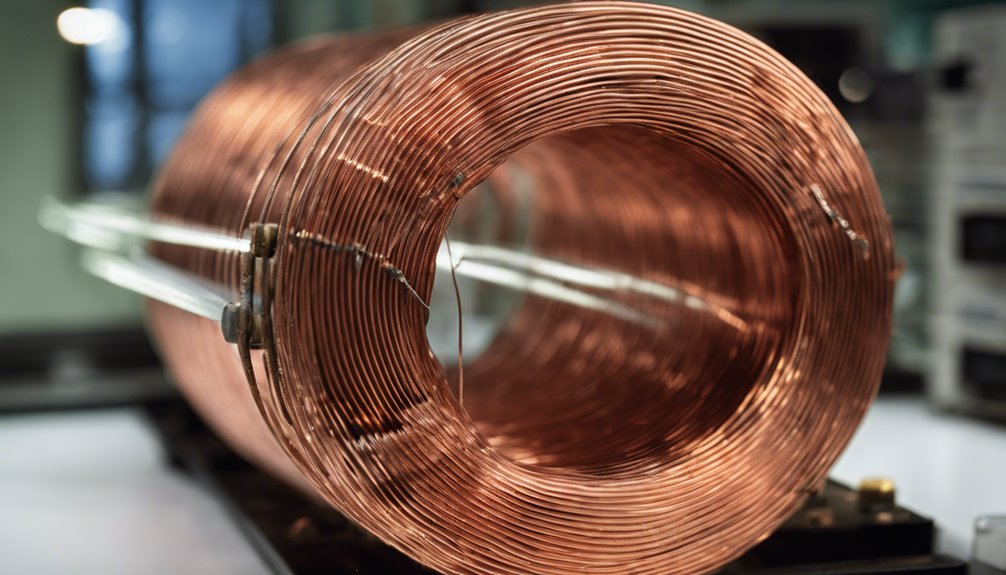
When you understand self-inductance, you encounter a fascinating property of circuits that allows them to resist changes in current. Self-inductance occurs when a change in current through a circuit induces a voltage that opposes the change, as Lenz’s Law dictates. This induced voltage is essential because it helps maintain stability within the circuit by counteracting fluctuations in current.
The fundamental equation E = -L(dI/dt) captures this relationship, where the negative sign highlights the opposition to change.
The self-inductance of a coil, measured in henries, depends greatly on the number of turns and the magnetic flux linking each turn. This relationship is mathematically expressed as L = N(ϕ/I). Here, ‘N’ represents the number of turns, ‘ϕ’ for magnetic flux, and ‘I’ for current. The greater the number of turns and magnetic flux, the higher the inductance, enhancing the coil’s ability to store energy in its magnetic field.
Additionally, the coil’s geometry and core material, such as ferromagnetic substances, can greatly influence its inductance, making it more effective at resisting changes in current. Understanding these factors helps you grasp the intricate nature of self-inductance.
Faraday’s Law and Self-Induction
With Faraday’s Law, you see that an induced electromotive force (emf) arises when there’s a change in magnetic flux through a circuit.
In self-induction, this principle means that the coil generates an opposing electromagnetic field when the current changes, as Lenz’s Law dictates.
The rate at which the current changes directly affects the magnitude of the induced emf, highlighting the vital role of self-inductance in regulating these dynamics.
Induced EMF and Direction
Understanding the induced electromotive force (EMF) concept is fundamental to examining Faraday’s Law and self-induction. When current changes in a circuit, the magnetic flux through that circuit is affected. According to Faraday’s Law, the induced EMF is directly proportional to the negative rate of change of this magnetic flux.
If you have a coil with multiple turns, the induced EMF increases with more turns, as expressed by the formula ε = -N(dΦ/dt). This means that as the rate of change in magnetic flux intensifies, the induced EMF rises, and its direction will oppose the change in current, a principle known as Lenz’s Law.
Self-duction plays an important role in this process. It’s the property of a coil that allows it to induce an EMF in itself when current changes occur. Self-inductance is measured in henries and is represented by the formula ε = -L(di/dt).
Lenz’s Law guarantees energy conservation by causing the direction Law, the induced EMF, to counteract any sudden changes in current flow. So, when dealing with circuits, understanding how self-inductance and induced EMF interact is critical to managing and predicting circuit behavior.
Rate of Current Change
Sometimes, the key to understanding electrical circuits is how rapidly the current changes. The rate of current change, or di/dt, directly impacts the induced EMF within a circuit. According to the self-inductance formula, E = -L(di/dt), the inductance (L) in Henries determines how much opposition the circuit will offer to changes in current.
Lenz’s law plays an essential role here, ensuring that the induced emfLawposes the change in current that caused it, effectively stabilizing the circuit.
Faraday’s law complements this concept, stating that the induced emf is proportional to the negative rate of change of magnetic flux, expressed as ε = -N(dΦ/dt). A coil’s self-inductance, a geometric property, hinges on its shape, core material, and number of turns, all of which affect magnetic flux linkage.
In alternating current (AC) circuits, frequency becomes a significant factor as inductive reactance (XL) increases with frequency, as described by XL = 2πfL. This relationship underscores how self-inductance affects circuits differently than direct current scenarios.
Understanding these principles provides a foundation for managing and predicting circuit behavior under varying electrical conditions.
Characteristics of Inductors
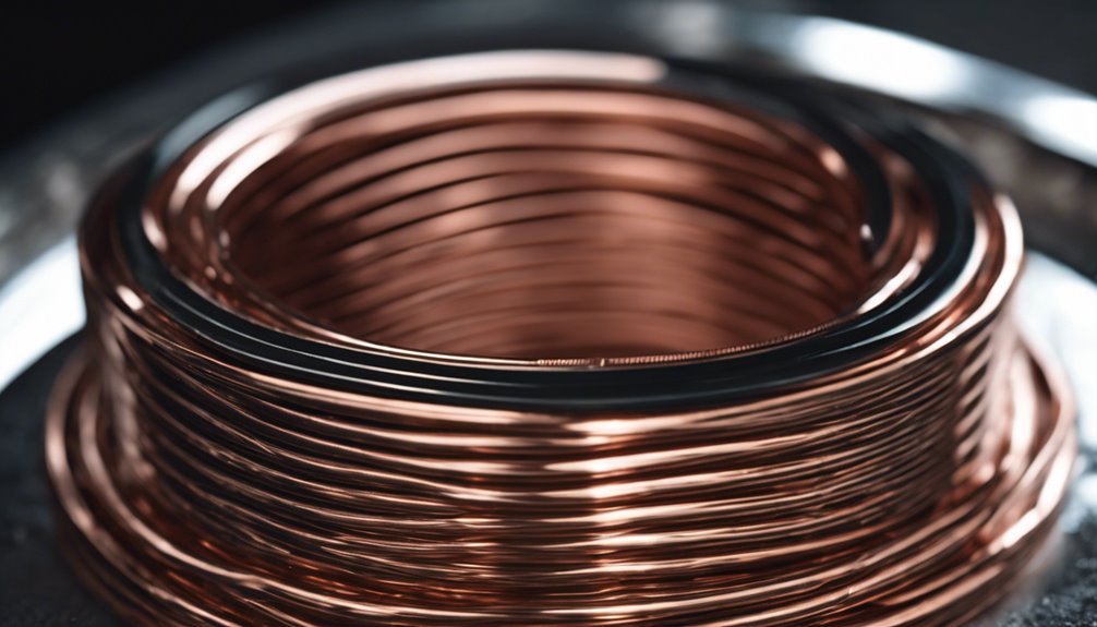
Exploring inductor’s characteristics reveals their essential role in electrical circuits. The inductor’s self-inductance is a significant property that defines how effectively it can store energy. When current flows through an inductor, it generates a magnetic field, and the energy stored is proportional to the current’s inductance and square.
As the current flow changes, the magnetic flux through the coil alters. This change induces a voltage across the inductor, adhering to Lenz’s Law. Inductance is defined by factors like the number of turns in the coil, the core material’s permeability, and the coil’s geometry.
Inductors are important in opposing changes in current, and they’re represented in circuit diagrams by a coiled wire symbol. Their opposition to alternating current is described by inductive reactance, which increases with frequency. This reactance is calculated using the formula (X_L = 2pi f L), where (f) is the frequency.
Lenz’s Law Explained
As you grasp the characteristics of inductors and their role in resisting changes in current, it becomes important to appreciate the underlying principles, like Lenz’s Law, that govern their behavior.
Lenz’s Law states that the direction of an induced current will always cause the change in magnetic flux that created it. This guarantees the conservation of energy within the system. Mathematically, this is represented by the induced electromotive force (emf) being negative, aligning with Faraday’s Law of electromagnetic induction. The formula E = -L(di/dt) highlights how the induced emf opposes the current change, maintaining energy balance within the circuit.
In practical terms, Lenz’s Law is essential for understanding how inductors behave in AC circuits. Here, the phase shifts of the induced current can greatly affect overall circuit performance.
It also plays a key role in phenomena like back EMF in motors, where the induced voltage opposes the applied voltage. This opposition is fundamental for efficient motor operation and highlights the importance of energy balance.
Inductive Reactance Overview
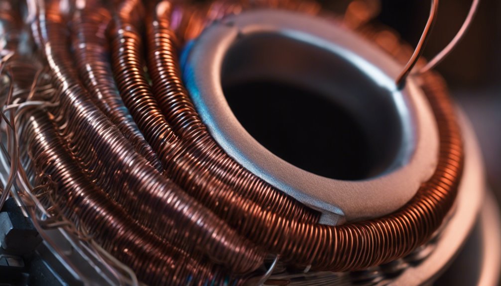
When you work with AC circuits, understanding inductive reactance is key to managing current flow reduction.
It directly affects the extent to which the current lags behind the voltage, creating a vital phase relationship in which the current lags by 90 degrees.
This lag can influence your circuit’s performance, especially when combined with other components.
Current Flow Reduction
Inductive reactance, indicated by (X_L), is important in reducing current flow through an inductor in AC circuits. The self-inductance of the coil causes the induction of a voltage that opposes the change in the current. This phenomenon is described by Lenz’s Law, which states that the induced current in the circuit will always act to oppose the change in the current that created it. As a result, inductive reactance effectively limits the amount of current allowed to flow through an inductor.
Consider these points to understand how inductive reactance affects current flow:
- Frequency Dependency: Inductive reactance increases with frequency. So, the inductor’s opposition to current flow is more significant at higher frequencies.
- Induced EMF: The change in current induces an EMF that resists any alterations in current flow, reducing overall current.
- Phase Difference: Although not detailed here, remember that the current lags the voltage, affecting the circuit’s behavior.
- Energy Conservation: Unlike resistance, inductive reactance doesn’t dissipate energy as heat; it temporarily stores energy in the magnetic field.
Understanding these aspects helps you appreciate how inductive reactance is important in controlling AC flow through inductors.
Phase Relationship in AC
When exploring the phase relationship in AC circuits, it’s vital to understand how inductive reactance influences the interaction between voltage and current. Inductive reactance (X_L) plays a significant role in dictating how the current flows relative to the voltage. Self-inductance, inherent in inductors, creates this reactance, which is calculated by the formula X_L = 2πfL.
As the frequency of the AC signal increases, so does the inductive reactance, which results in less current flowing through the circuit.
You’ll notice a phase difference in these circuits, where the current lags behind the voltage by 90 degrees (π/2 radians). This lag occurs because an ideal inductor requires time to build up its magnetic field, causing the voltage to peak before the current does.
This phase difference and inductive reactance contribute to the complex impedance in AC circuits. Properly understanding these dynamics helps predict circuit behavior, especially during resonance conditions.
When the inductive and capacitive reactances balance, the circuit can achieve maximum current flow at a specific frequency. This knowledge is important for designing efficient circuits and optimizing their performance.
Solenoids and Self Inductance
To explore the fascinating world of solenoids and self-inductance, let’s first consider a solenoid—a coil of wire designed to generate a uniform magnetic field as current flows through it.
The self-inductance of a solenoid is essential in determining how efficiently it can store energy in its magnetic field. Here’s what influences this:
- Number of Turns (N): More turns mean more magnetic flux linking each turn, enhancing the solenoid’s inductance and storage capacity.
- Magnetic Field Strength: The solenoid’s geometry, including its cross-sectional area (A) and length (l), impacts the magnetic field strength, affecting the energy stored.
- Current Flowing (I): The magnetic flux (Φ_m) through each turn is directly proportional to the current, described by Φ_m = (μ₀NA/l)I. This relationship is significant for understanding the solenoid’s self-inductance.
- Inductance (L): Calculated using L = (μ₀N²A)/l, this formula shows how solenoid design affects its ability to store magnetic energy.
Solenoids exhibit strong self-inductance due to their shape, effectively storing energy in a magnetic field.
This property is vital for various applications and is a foundation for understanding how energy is managed and utilized in electrical circuits.
Practical Applications of Inductors
Practical applications of inductors are all around us, often unnoticed but incredibly important. You’ll find inductors smoothing out voltage fluctuations in power supply circuits. They store energy in a magnetic field, releasing it when needed to reduce ripple voltage. This is vital for keeping your electronics running smoothly. Inductors work based on the principle that a changing current in a current-carrying wire induces a magnetic field.
In traffic signal systems, inductors are key. They detect vehicles by measuring circuit changes caused by the presence of metal, which alters inductance and triggers signal changes. This process obeys Lenz’ss Law, where the induced current opposes the change in the magnetic field lines.
Metal detectors also rely on inductors. They create oscillating magnetic fields that induce currents in nearby metal objects. The induced signals help identify various metals based on their response.
In-camera flash circuits, inductors collaborate with transformers to step up the voltage. They produce the high voltage necessary for quick, bright flashes.
Finally, in audio equipment, inductors in LC filter circuits play a pivotal role. They eliminate unwanted frequencies, allowing desired signals through and ensuring quality sound.
Calculating Inductive Properties
Calculating inductive properties involves understanding how various factors contribute to an inductor’s behavior in a circuit. To determine self-inductance, you can start by considering the solenoid formula: L = (μ₀N²A)/l. Here, μ₀ is the permeability of free space, N is the number of turns, A is the cross-sectional area, and l is the solenoid’s length. Each of these factors plays a significant role in calculating self-inductance.
To calculate the induced electromotive force (emf) in a coil, use the equation ε = -L(dI/dt). This accounts for the induced emf due to the current change rate through the inductor. For a practical approach, rearrange this equation to find L: L = |ε|/|dI/dt|. This allows you to calculate self-inductance directly from measured values.
Here’s a simplified breakdown:
- Self-Inductance Formula: L = (μ₀N²A)/l.
- Induced EMF Formula: ε = -L(dI/dt).
- Calculate Self-Inductance: L = |ε|/|dI/dt|.
- Measurement Tools: Use LCR meters or resonance frequency methods for accuracy.
Self-Inductance in Circuit Design

In circuit design, self-inductance is an important element that directly impacts how inductors react to current changes, affecting stability and transient responses. When current increases in a circuit, self-inductance causes a delay, storing energy in the magnetic field. This energy storage is essential for voltage regulation, guaranteeing the circuit’s stability despite fluctuations.
To calculate self-inductance in solenoids, use the formula L = (μ₀N²A)/l, where each variable plays a role in determining the inductor’s behavior.
In AC circuits, self-inductance contributes to inductive reactance, calculated as X_L = 2πfL. This reactance affects the circuit’s impedance, influencing how it handles different frequencies.
As a circuit designer, you must have appropriate inductor values for effective filtering and energy storage, especially in power supplies and oscillators.
Self-inductance also causes phase shifts, with current lagging voltage 90 degrees in pure inductive scenarios. This lagging effect is fundamental in designing resonant circuits and tuned amplifiers, where precise timing guarantees peak performance.
Understanding and accounting for these factors will enhance your circuit design, leading to more efficient and reliable electronic systems.
Conclusion
You’ve explored the fascinating world of self-inductance, a key player in electrical circuits. By understanding Faraday’s and Lenz’s laws, you see how inductors help stabilize current and manage energy. You’ve learned about the characteristics of inductors, the role of solenoids, and how to calculate inductive properties. This knowledge empowers you to effectively integrate self-inductance into circuit design, enhancing power supply and signal processing application performance. Remember, mastering self-inductance means mastering control over electrical systems.
FAQs
1. What Is Self-Inductance in Simple Words?
Self-inductance occurs when magnetic fields from electric currents create inductive reactance, affecting circuit behavior. Faraday’s law explains how energy storage in coil design leads to inductoLawpplications. It helps manage the current flow and stabilize circuits.
2. What Is L in Self-Inductance?
You’re curious about “L” in self-inductance. It represents how a coil stores energy in magnetic fields, affecting circuit applications. Coil design and inductor types influence L, which is measured using techniques considering frequency response and Lenz’s law.
3. What Is the Difference Between Inductance and Self-InduLawnce?
Inductance is a broad concept involving multiple circuits, while self-inductance focuses on one. Consider inductor types in AC circuits, where magnetic fields and energy storage play roles, guided by Lenz’s law and transformer principles.
4. What Is the Formula for Self-Induction?
You’ll find the formula for self-induction is L = NΦ/I. It considers self-inductance effects and uses inductance units. This relates to magnetic fields and energy storage and is essential in circuit applications, coil design, and self-induction experiments.
