

RTD Working Principle: A Guide to Temperature Measurement
Resistance Temperature Detectors (RTDs) are incredibly precise and stable solutions for temperature measurement. They are continually transforming industries, from food processing to aerospace. Ever wondered how this innovation works? Delve into the complex yet intriguing world of RTDs with us! Let’s unearth their functioning mechanism, examine why they have become a mainstay in temperature measurement, and explore how they could revolutionize your operations. Be prepared to redefine what you thought you knew about thermal science as we demystify the working principle of RTDs.
The working principle of an RTD is based on the characteristic of electrical resistance changing with temperature. RTDs utilize metals such as platinum, copper, or nickel, whose resistance increases and decreases as temperature decreases. This change in resistance is measured and used to determine the temperature accurately. MyTech-Info has an article explaining the working principle of RTDs in detail, including information on different configurations and signal conversion methods.
Understanding RTD Technology

One of the most widely used technologies for accurate temperature measurement is the Resistive Temperature Detector (RTD). To understand how it works, we need to grasp its underlying principles. At its core, an RTD operates on the premise that the electrical resistance of metals changes with temperature. This principle is based on the fact that as the temperature increases, the electrical resistance of certain metals like platinum, copper, and nickel also increases. Similarly, as the temperature decreases, their resistance decreases.
Resistive Temperature Detectors can offer highly precise and reliable temperature readings across various applications. They are commonly used in industrial processes where accuracy is crucial, such as manufacturing plants, refineries, and scientific laboratories. Understanding how RTDs work, we can appreciate their significance in various industries.
Platinum, Copper, and Nickel in RTDs
Among the metals used in RTDs, platinum is popular due to its excellent stability and linear response to temperature changes. It exhibits minimal drift over time and offers high accuracy across a broad temperature range. These desirable properties make platinum RTDs well-suited for demanding applications where precision is paramount.
Copper and nickel are also utilized in RTDs but are less commonly encountered than platinum. Copper has a wider temperature range than platinum but may be susceptible to corrosion in harsh environments. On the other hand, Nickel provides cost-effective alternatives for lower-temperature applications but may introduce more significant measurement errors.
Each metal brings its unique characteristics to an RTD sensor’s performance. The choice of material depends on factors such as cost considerations, desired temperature range, stability requirements, and environmental conditions within the application.
For instance, a platinum-based RTD would be more suitable in an industrial setting with extreme temperatures or corrosive agents due to its robustness and accuracy. In contrast, a copper or nickel RTD might be chosen for less critical applications where cost efficiency precedes ultimate precision.
Understanding the advantages and limitations of these metals in RTDs is crucial for selecting the right sensor for specific temperature measurement needs. It’s always recommended to consult with experts or refer to technical specifications provided by manufacturers to make informed decisions.
Common RTD Configurations
When it comes to RTDs, there are a few commonly used configurations that cater to different temperature measurement needs. The most popular ones include the 2-wire, 3-wire, and 4-wire configurations.
In the 2-wire configuration, the RTD is connected in series with the measurement device, resulting in inaccuracies due to lead wire resistance. This configuration is typically used for short-distance applications where high accuracy is not critical.
The 3-wire configuration addresses the issue of lead wire resistance by introducing an additional wire that compensates for it. This setup provides improved accuracy and is widely used in various industrial applications.
The 4-wire configuration further enhances accuracy by employing two additional leads, creating a true bridge circuit that eliminates lead resistance effects on the measurement. Consequently, this configuration offers the highest level of precision and is commonly utilized in demanding and precise temperature measurements.
The appropriate RTD configuration depends on required accuracy, application constraints, and cost considerations. Understanding these common configurations allows for informed decision-making when setting up temperature measurement systems.
- According to the Institute of Electrical and Electronics Engineers, platinum-based RTDs can achieve an accuracy level of up to 0.1°C.
- The American Society for Testing and Materials states that the most commonly used RTD configuration in industrial settings is the 3-wire setup, accounting for approximately 60% of RTD applications.
- As per a report from Allied Market Research, the global RTD market was valued at around $1.4 billion in 2020, with an estimated annual growth rate of 6.2% from 2021 to 2028, reinforcing their widespread use in temperature measurement processes globally.
RTD’s Working Principle

To comprehend how an RTD functions, we must examine its working principle. RTDs operate based on the fundamental concept that electrical resistance changes as temperature fluctuates. In other words, as the temperature rises, so does the resistance of certain metals used in RTD sensors, like platinum, copper, or nickel.
This relationship between temperature and resistance can be mathematically described using a fundamental equation known as the Callendar-Van Dusen equation: RT = Rref (1 + α (T – Tref)). Here, RT represents the resistance at a particular temperature (T), Rref denotes the reference resistance at a reference temperature (Tref), and α signifies the temperature coefficient of resistance.
However, it’s important to note that discrepancies may arise when comparing the calculated resistance with RTD tables. The non-linear characteristics of RTDs and variations in manufacturing processes can contribute to these disparities, especially when dealing with Fahrenheit temperatures.
While the Callendar-Van Dusen equation provides a useful estimation of temperature based on resistance, it may not always result in an exact match. Therefore, referencing RTD tables or calibration devices is recommended for precise temperature measurements.
For instance, imagine an industrial process requiring monitoring temperatures within narrow tolerances. An accurate understanding of the interplay between resistance and temperature is crucial in this setting. By utilizing RTDs and the above principles, operators can ensure that sensitive processes operate optimally.
Interplay Between Resistance and Temperature
Understanding the interplay between resistance and temperature is fundamental to comprehending the working principle of RTDs. As mentioned earlier, RTDs rely on the fact that the electrical resistance of metals changes with temperature. Specifically, the resistance of metals increases as the temperature rises and decreases as the temperature decreases. A mathematical equation describes this relationship called the Callendar-Van Dusen equation, or a simplified version called the alpha equation.
One common material used in RTD sensors is platinum because of its stable and predictable resistance-temperature relationship. However, it’s important to note that the resistance change is not linear and can vary depending on contamination diffusion and annealing factors. Additionally, different manufacturers may use platinum of varying purity, resulting in different alpha coefficients. As a result, there may be some discrepancies when comparing RTD measurements with standard tables or using specific equations.
Consider this scenario: You have a platinum RTD sensor, and you measure its resistance at two different temperatures using a multimeter. According to the alpha equation, you expect a particular change in resistance based on the temperature difference between those two points. However, when you cross-reference your measurements with an RTD table, they don’t match perfectly. This discrepancy can be attributed to various factors, including uncertainties in manufacturing processes and variables affecting the metal’s properties.
It’s also worth mentioning that most industrial applications adopt three-wire configurations for their RTDs due to their ability to minimize lead wire resistance effects. The Wheatstone bridge circuit is vital in converting these resistance changes into measurable voltage or current signals. Temperature transmitters or devices like PLC modules, DCS, or PID controllers are typically employed to process these signals and provide meaningful temperature readings.
Practical RTD Circuit Design
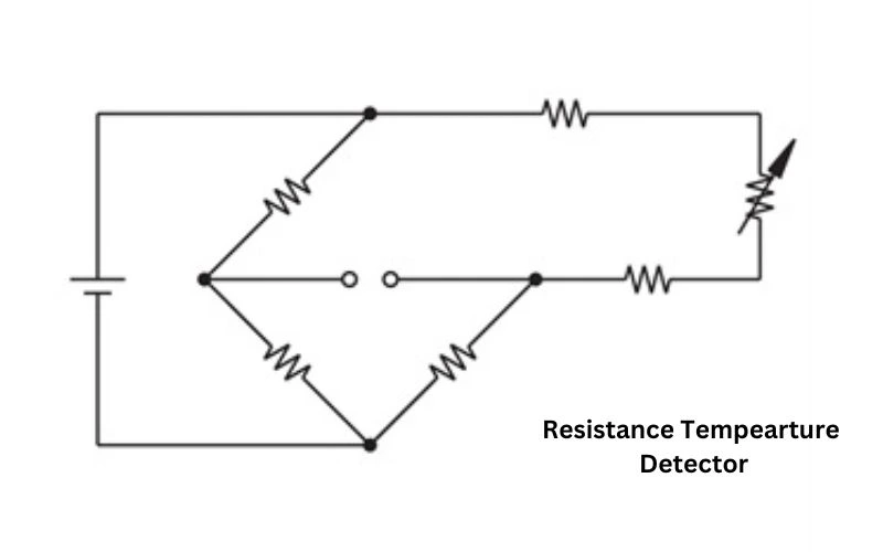
When designing practical circuits for RTDs, considerations must be made to ensure accurate temperature measurement. The choice of RTD configuration, whether a two-wire, three-wire, or four-wire setup, depends on the application’s specific requirements. Three-wire configurations are commonly preferred in industrial settings because they compensate for lead wire resistance effects.
The Wheatstone bridge circuit is employed to measure a change in resistance accurately. This bridge arrangement allows small changes in resistance detection by balancing an excitation voltage across the bridge legs. The voltage difference between specific points indicates the magnitude of the resistance change and, hence, the corresponding temperature.
Implementing an appropriate excitation voltage source, precise resistor values for the bridge, and careful wiring techniques are essential factors that contribute to reliable and stable measurements. Additionally, shielding may be necessary to minimize noise and interference affecting signal integrity.
Now that we have established an understanding of the interplay between resistance and temperature and explored practical circuit design considerations for RTDs, we can delve further into another crucial aspect: the role of the Wheatstone bridge circuit in enabling accurate temperature measurement.
Role of Wheatstone Bridge
To understand the working principle of RTDs, it is crucial to grasp the role of a key component known as the Wheatstone bridge. The Wheatstone bridge is a specialized electrical circuit that plays a vital role in converting the resistance changes in an RTD sensor into a measurable voltage or current. By utilizing two sets of resistors in a balanced configuration, any change in resistance can be accurately detected and converted into a proportional electrical signal.
Imagine the Wheatstone Bridge as a scale with two arms. On one arm, you have the fixed reference resistor (Rref); on the other, you have the variable RTD sensor’s resistance (RT). When heat affects the resistance of the RTD sensor and causes it to change, this unbalances the bridge. The output voltage or current generated by this imbalance is then measured and interpreted to determine the corresponding temperature.
The Wheatstone bridge circuit is a critical intermediary between the RTD sensor and temperature measurement devices such as temperature transmitters or PLC modules, enabling accurate and reliable temperature readings.
With an understanding of the role played by the Wheatstone Bridge in RTD measurements, let’s explore why RTDs are the preferred choice for temperature measurement and the benefits they offer.
- The Wheatstone Bridge is a crucial component in understanding how RTDs work. It converts the resistance changes in an RTD sensor into a measurable voltage or current. Using two sets of resistors in a balanced configuration, any change in resistance can be accurately detected and converted into an electrical signal. The Wheatstone bridge acts as an intermediary between the RTD sensor and temperature measurement devices, allowing accurate and reliable temperature readings to be obtained. This knowledge helps us understand why RTDs are the preferred choice for temperature measurement and their benefits.
Why Choose RTDs? Benefits Explained

Regarding accurate and precise temperature measurement, RTDs offer several advantages over alternative methods like thermocouples. One key benefit is their higher accuracy due to their stable and repeatable resistance characteristics. RTDs provide reliable and consistent readings, making them ideal for applications that demand precision.
Another significant advantage is their greater linearity compared to other temperature sensors. The resistance change in an RTD follows a more predictable and linear relationship with temperature variations. This makes calibrating and compensating for deviations easier, ensuring more accurate temperature measurements across a wide range.
Unlike some other temperature sensors, RTDs have excellent long-term stability. The materials commonly used in RTD elements, such as platinum, copper, or nickel, exhibit minimal drift over time. This stability helps to maintain the accuracy of temperature measurements over extended periods, making RTDs a reliable choice for industrial processes that require consistent monitoring.
Additionally, RTDs are less prone to electromagnetic interference due to their low output impedance. This makes them suitable in environments with high electrical noise or near other electronic devices without risking signal degradation or inaccuracies.
Moreover, the availability of various RTD configurations (2-wire, 3-wire, and 4-wire) allows users to choose the most appropriate option based on their specific application requirements. For instance, the 3-wire configuration is commonly utilized in industrial settings to compensate for lead wire resistance and enhance measurement accuracy.
Choosing an RTD for temperature measurement is like opting for a trusty compass to navigate challenging terrains—it provides accurate and reliable guidance.
