

Resistance Deconstructed: Exploring Color Codes and Calculations
In the intricate realm of electronics and electrical engineering, where precision is paramount, the unassuming yet vital component known as resistance plays a pivotal role. Among the various tools at the disposal of engineers and enthusiasts, understanding resistance color codes and calculations stands as a fundamental skill. This journey delves into the heart of resistors, unraveling the mystery behind the colorful bands that adorn them and the intricate calculations that determine their values. With each colored stripe representing a vital piece of information, we embark on a quest to decode these color codes and explore the mathematical underpinnings that bring resistors to life. By demystifying these seemingly enigmatic codes and calculations, we empower ourselves to navigate circuits precisely, ensuring that every component aligns harmoniously to get our electrical creations to fruition.
Resistor Markings and Specifications
Resistors are offered in various resistance values from a fraction of Ohms (Ω) to millions of Ohms. The resistance values, tolerance, and power rating are usually written on top of the body of resistors as nos. or letters. In contrast, the body of the resistors is vast and adequate to read the print, such as high power resistors.

Charge and the Electric Current
Charge and electric current are fundamental concepts at the heart of our understanding of electricity. Charge refers to the actual property of matter that gives rise to electric forces and interactions. It is the source of all electrical phenomena and can exist in positive and negative forms. On the other hand, electric current is the flow of electric charge through a conductor. It represents the movement of charged particles, such as electrons, in response to an electric field. Current is measured in units of amperes (A) and is crucial for powering our homes, driving electronic devices, and fueling technological advancements. Understanding the behavior of charge and the flow of electric current is essential for comprehending the intricate workings of circuits, designing electrical systems, and harnessing the power of electricity in various applications. By exploring these concepts, we gain insights into the very foundation of our electrified world, empowering us to unlock new possibilities and revolutionize how we live, work, and connect.
Resistors color code
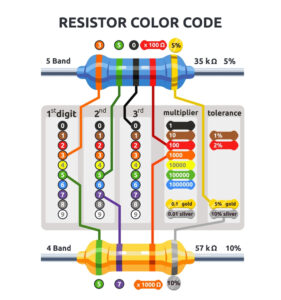
The resistors’ resistance is noticeable on the body of the resistors with color code bands that indicate values.
Magnetic Flux / Magnetic Flux Density
Magnetic Flux and Magnetic Flux Density are two fundamental concepts that provide us with a deeper understanding of the invisible yet captivating world of magnetism. Magnetic Flux is a measure of the magnetic field passing through a given surface, representing the total number of magnetic field lines penetrating that surface. It provides a window into the strength and extent of magnetic fields, revealing their influence and reach. On the other hand, Magnetic Flux Density, also known as magnetic field strength, refers to the concentration and intensity of magnetic field lines within a given area.
It provides valuable insights into the magnitude of magnetic forces and their effects on nearby objects or materials. These concepts illuminate the intricate interplay between magnets, magnetic fields, and the environment. By exploring Magnetic Flux and Magnetic Flux Density, we unlock the door to a realm where unseen forces shape our physical reality, paving the way for technological breakthroughs, scientific discoveries, and a deeper appreciation of the marvels of magnetism.
Color Codes
-
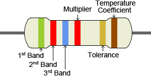
4-bands: digit, digit, multiplier, tolerance.
-
5-bands: digit, digit, digit, multiplier, tolerance.
-
6-bands: digit, digit, digit, multiplier, tolerance, temperature coefficient.
Resistance calculation of 4 bands resistor
To calculate the resistance of a 4-band resistor, you need to understand the color code and interpret the color bands correctly. The color bands on the resistor represent different digits or values that determine its resistance. The standard color code for a 4-band resistor includes three color bands for the significant figures and one for the multiplier.
Here is the step-by-step process for calculating the resistance of a 4-band resistor:
Identify the color of each band
Start by observing and noting down the color of each band from left to right. The first band represents the first significant figure, the second band represents the second important figure, the third band represents the multiplier, and the fourth band represents the tolerance.
Determine the significant figures.
Assign the corresponding numerical value to each influential figure color band based on the standard color code. Refer to a resistor color code chart or table to determine the numerical values associated with each color. Note down the numerical values for the first two bands.
Determine the multiplier
Look at the color of the third band, representing the multiplier. Again, consult the color code chart to associate the color with the multiplier value. Common multiplier values include 1 (no color), 10 (black), 100 (brown), 1,000 (red), and so on. Multiply the significant figures obtained in step 2 by the multiplier value to obtain the resistance value in ohms.
Determine the tolerance
The fourth band represents the tolerance, indicating the allowable deviation from the stated resistance value. Use the color code chart to determine the tolerance value associated with the color. Common tolerance values include ±1% (brown), ±5% (gold), and ±10% (silver).
Calculate the resistance
Combine the significant figures from step 2 with the multiplier obtained in step 3 to obtain the resistance value in ohms. For example, if the influential figures are 2 and 4, and the multiplier is 1,000, the resistance would be 24,000 ohms or 24 kilohms.
Remember to refer to a reliable color code chart or table to ensure an accurate interpretation of the resistor’s color bands.
Resistance calculation of 5 bands resistor

Resistance = (Significant Figure 1 * 100 + Significant Figure 2 * 10 + Significant Figure 3) * Multiplier.
To calculate the resistance of a 5-band resistor, you need to understand the color code and interpret the color bands correctly. The color bands on the resistor represent different digits or values that determine its resistance. The standard color code for a 5-band resistor includes the following:
- Three color bands for the significant figures.
- One color band for the multiplier.
- One color band for tolerance.
Here is the step-by-step process for calculating the resistance of a 5-band resistor:
Identify the color of each band
Start by observing and noting down the color of each band from left to right. The first band represents the first significant figure, the second band represents the second important figure, the third band represents the third influential figure, the fourth band represents the multiplier, and the fifth band represents tolerance.
Determine the significant figures.
Assign the corresponding numerical value to each influential figure color band based on the standard color code. Refer to a resistor color code chart or table to determine the numerical values associated with each color. Note down the numerical values for the first three bands.
Determine the multiplier
Look at the color of the fourth band, representing the multiplier. Again, consult the color code chart to associate the color with the multiplier value. Common multiplier values include 1 (no color), 10 (black), 100 (brown), 1,000 (red), and so on. Multiply the significant figures obtained in step 2 by the multiplier value to obtain the resistance value in ohms.
Determine the tolerance
The fifth band represents the tolerance, indicating the allowable deviation from the stated resistance value. The color code chart will provide the corresponding percentage values for each color. Common tolerance values include ±1% (brown), ±5% (gold), and ±10% (silver).
Calculate the resistance: Combine the significant figures from step 2 with the multiplier obtained in step 3 to obtain the resistance value in ohms. For example, if the important figures are 2, 4, and 7, and the multiplier is 1,000, the resistance would be 247,000 ohms or 247 kilohms.
Remember, using a reliable color code chart or table is essential to accurately interpret the resistor’s color bands.
Resistance calculation of 6 bands resistor
Resistance = (Significant Figure 1 * 100 + Significant Figure 2 * 10 + Significant Figure 3) * Multiplier
To calculate the resistance of a 6-band resistor, you need to understand the color code and interpret the color bands correctly. The color bands on the resistor represent different digits or values that determine its resistance. The standard color code for a 6-band resistor includes the following:
- Three color bands for the significant figures.
- One color band for the multiplier.
- One color band for tolerance.
- One color band for the temperature coefficient.
Here is the step-by-step process for calculating the resistance of a 6-band resistor:
Identify the color of each band
Start by observing and noting down the color of each band from left to right. The first band represents the first significant figure; the second band represents the second important figure; the third band represents the third influential figure; the fourth band represents the multiplier; the fifth band represents the tolerance; and the sixth band represents the temperature coefficient.
Determine the significant figures.
Assign the corresponding numerical value to each influential figure color band based on the standard color code. Refer to a resistor color code chart or table to determine the numerical values associated with each color. Note down the numerical values for the first three bands.
Determine the multiplier
Look at the color of the fourth band, representing the multiplier. Again, consult the color code chart to associate the color with the multiplier value. Multiply the significant figures obtained in step 2 by the multiplier value to obtain the resistance value in ohms.
Determine the tolerance
The fifth band represents the tolerance, indicating the allowable deviation from the stated resistance value. Use the color code chart to determine the tolerance value associated with the color. Common tolerance values include ±1% (brown), ±5% (gold), and ±10% (silver).
Determine the temperature coefficient.
The sixth band represents the temperature coefficient, which indicates how the resistance changes with temperature. Consult the color code chart to determine the temperature coefficient value associated with the color. Common temperature coefficient values include 100 ppm/°C (brown), 50 ppm/°C (red), and 15 ppm/°C (blue).
Calculate the resistance
Combine the significant figures from step 2 with the multiplier obtained in step 3 to obtain the resistance value in ohms. For example, if the important figures are 2, 4, and 7, and the multiplier is 1,000, the resistance would be 247,000 ohms or 247 kilohms.
Consider the tolerance and temperature coefficient values if they are provided, as they can affect the actual resistance value. Always refer to a reliable color code chart or table to ensure an accurate interpretation of the resistor’s color bands.
