

Navigating the Open Circuit Test or No Load Test for Transformer
Transformer testing plays a pivotal role in ensuring the reliability and efficiency of electrical power systems. Among the various tests conducted on transformers, the Open Circuit Test, also known as the No Load Test, stands out as a crucial diagnostic procedure. This article aims to delve into the intricacies of the Open Circuit Test, offering a comprehensive overview of its purpose, procedure, and significance in transformer design and evaluation. By examining the core losses, magnetizing current, and efficiency under no-load conditions, engineers and technicians can glean valuable insights into a transformer’s performance, aiding in optimization and troubleshooting.
In addition to exploring the Open Circuit Test, this article will touch upon the Short Circuit Test, another essential evaluation that provides a holistic understanding of a transformer’s behavior. By introducing both tests, this article aims to equip professionals with a thorough understanding of how these diagnostic tools contribute to transformer quality control, maintenance, and overall operational excellence in electrical power systems.
Key Takeaways
- Purpose: The open circuit test is conducted to determine the core losses (iron losses) and the magnetizing current of the transformer. It is typically performed on the high-voltage winding with the low-voltage winding left open.
- Procedure: Apply rated voltage to the primary winding (high-voltage side) while keeping the secondary winding (low-voltage side) open. Use appropriate meters to measure the input voltage, current, and power.
- Core Losses: The power measured during the open circuit test represents the core losses (hysteresis and eddy current losses) since the secondary side is open and no load is connected.
- Magnetizing Current: The current measured in the primary winding during this test is the magnetizing current, which is required to establish the magnetic flux in the core.
- No Load Condition: This test is performed under no load condition, meaning the secondary winding is not supplying any load, thus the current drawn is solely for magnetizing the core and compensating for the core losses.
- Voltage Measurement: The applied voltage is usually the rated voltage of the primary winding, and it helps determine the transformer’s no-load parameters. Precautions: Ensure proper safety measures as high voltage is involved in the open circuit test. Adequate insulation and grounding are necessary to prevent any accidents.
No Load Test for Transformers
This test determines the no-load loss or core loss and no-load Io, which is beneficial to finding the results of X0 and R0.
Test Setup and Equipment
One winding of the transformer is left open, and the other is connected to its supply of standard voltage and frequency. A wattmeter-W, voltmeter-V, and an ammeter-A are connected within the low-tension winding (primary coil). The usual flux is found within the core with standard voltage applied to the primary.
Conductance Calculation
- A high-resistance voltmeter is occasionally connected across the secondary to determine the induced e.m.f.
- This helps calculate the transformation ratio, K.
No-Load Vector Diagram
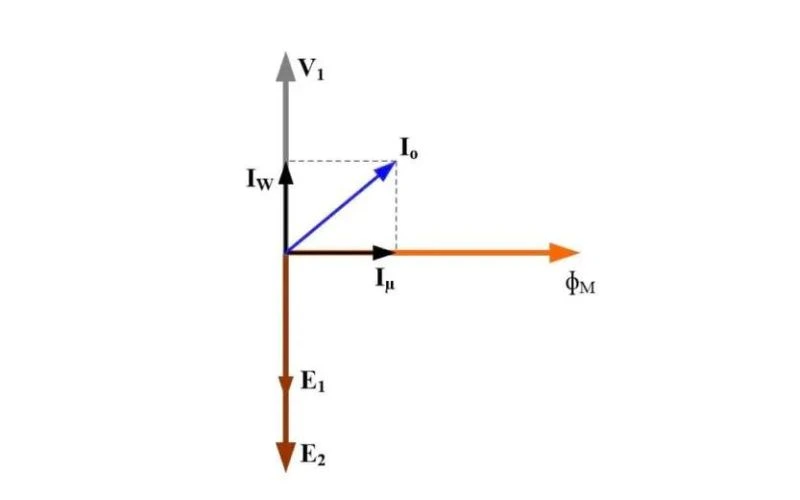
- The wattmeter reading (W) is crucial in determining core loss components.
- W = V1I0cosø0, where cosø0 = W/(V1I0).
- Exciting current components: Iµ = I0sinø0, IW = I0cosø0.
- Reactance and resistance components: X0 = V1/Iµ and R0 = V1/IW.
Power Factor and Conductance Calculation
- Since the current is almost all-exciting when a transformer is on no-load, Io = Iµ.
- G0 = W/V12 gives the exciting conductance G0.
- The exciting susceptance B0 = Sqr.(Y02 – G02).
Purpose of the Open Circuit Test
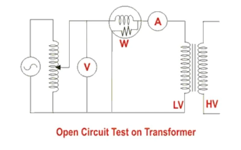
The Open Circuit Test evaluates a transformer’s core losses and magnetizing current when there is no load on the secondary side. The primary objective of this test is to assess the transformer’s efficiency and magnetic characteristics. The test helps determine the iron losses, which consist of hysteresis and eddy current losses, occurring in the transformer’s core under no-load conditions. Additionally, the test provides valuable information about the magnetizing current required to establish the magnetic field in the body.
Evaluating Core Losses
The Open Circuit Test primarily aims to determine a transformer’s core losses, which consist of hysteresis and eddy current losses in the magnetic core. These losses represent the energy dissipated in the body as heat and are crucial for evaluating the transformer’s efficiency.
Assessing Efficiency
By measuring the core losses during the Open Circuit Test, engineers can determine the transformer’s efficiency when operating under no-load conditions. Efficiency is a key performance metric that indicates the transformer’s ability to convert electrical power to usable output power while minimizing losses. The Open Circuit Test provides insights into the transformer’s efficiency at light loads, where core losses dominate.
Understanding Magnetizing Current
The Open Circuit Test also helps determine the magnetizing current required to establish the magnetic field in the transformer’s core. Magnetizing current is essential for creating the necessary magnetic flux in the transformer and is responsible for magnetizing the core. By measuring and analyzing the magnetizing current, engineers can gain insights into the transformer’s magnetic characteristics and evaluate the core’s performance.
Quality Control in Manufacturing
The Open Circuit Test is widely employed as a quality control measure during transformer manufacturing. By conducting this test on newly manufactured transformers, manufacturers can validate their performance and identify any discrepancies or deviations from desired specifications. It helps ensure that the transformers meet the required efficiency and performance standards before being deployed in electrical power systems.
Diagnostic Tool for Maintenance
The Open Circuit Test is a transformer maintenance and condition assessment diagnostic tool. Periodic testing of transformers helps monitor their health and detect any significant changes in core losses or magnetizing current. Deviations from expected test results can indicate potential issues or degradation, prompting further investigation and necessary maintenance actions.
Short Circuit Test

In addition to the Open Circuit Test, the Short Circuit Test is another essential evaluation for transformers. This test assesses the transformer’s behavior under short-circuit conditions, helping determine its impedance, power loss, and temperature rise.
Test Procedure and Equipment
The Short Circuit Test involves applying a short circuit on the secondary side while keeping the primary side connected to a reduced voltage. Instruments such as voltmeters, ammeters, and wattmeters measure parameters during the test.
Circuit Parameters
- Short circuit on the secondary side.
- Voltmeters measure the applied voltage.
- Ammeters measure the secondary current.
- Wattmeters measure the input power.
Analysis and Interpretation
- Data calculates the transformer’s impedance, power loss, and temperature rise.
- This test is crucial for evaluating the transformer’s performance under different loading conditions.
Conclusion
In conclusion, the Open Circuit Test, or Noad Test, is a critical component of transformer testing and evaluation. The test provides valuable insights into the transformer’s efficiency, design optimization, and overall performance by analyzing a transformer’s core losses and magnetizing characteristics under no-load conditions. It is a diagnostic tool for maintenance and troubleshooting purposes, enabling engineers and technicians to ensure the reliable and efficient operation of transformers in electrical power systems. The Short Circuit Test complements the Open Circuit Test by assessing the transformer’s behavior under short-circuit conditions and comprehensively evaluating its performance characteristics.
FAQs
What is the purpose of an open circuit test for a transformer?
An open circuit test for a transformer aims to determine the core losses (iron losses) and the magnetizing current when the transformer operates at its rated voltage. This test helps assess the transformer’s efficiency and performance without the influence of load losses.
How is the open circuit test for a transformer performed?
The open circuit test is performed using the following steps:
- Connect Equipment: Connect a voltmeter, ammeter, and wattmeter to the transformer’s high voltage (primary) side. Ensure the secondary winding (low voltage side) is open (no load connected).
- Apply Rated Voltage: To ensure precise control, apply the rated voltage to the primary winding using a variable voltage supply (autotransformer).
- Record Measurements: Measure and record the voltage (V1), no-load current (I0), and no-load power (P0) from the voltmeter, ammeter, and wattmeter, respectively.
- Calculate Core Losses: The power reading (P0) on the wattmeter represents the transformer’s core losses (iron losses) since the secondary winding is open and there is no load on it.
What are the key parameters measured in an open circuit test?
The key parameters measured in an open circuit test are:
- No-Load Voltage (V1): The voltage applied to the primary winding.
- No-Load Current (I0): The current flowing through the primary winding with the secondary winding open.
- No-Load Power (P0): The power the transformer consumes during the open circuit test represents the core losses.
How do you calculate core losses and magnetizing current from the open circuit test?
From the open circuit test, you can calculate the core losses and magnetizing current as follows:
- Core Losses (P_core): The power reading from the wattmeter (P0) represents the transformer’s core losses.
- Magnetizing Current (I_m): The no-load current (I0) consists of two components: the magnetizing current (I_m) and the core loss component (I_w). However, I0 is often considered the magnetizing current for simplicity since the core loss component is relatively small.
Why is the open circuit test conducted on the high-voltage side of the transformer?
The open circuit test is conducted on the high-voltage side of the transformer because:
- Convenience: Lower current values make it easier to measure small currents accurately on the high-voltage side.
- Safety: Working with lower current values on the high voltage side is generally safer and reduces the risk of overheating the primary winding during the test.
What are the benefits of conducting an open circuit test on a transformer?
The benefits of conducting an open circuit test on a transformer include:
- Efficiency Analysis: Helps determine the core losses, which are crucial for assessing the efficiency of the transformer.
- Performance Evaluation: Provides insights into the magnetizing current and the no-load behavior of the transformer.
- Design Verification: Helps verify the design parameters and ensure the transformer meets its specified performance criteria.
How does the open circuit test compare to the short circuit test?
The open circuit test and short circuit test are complementary tests used to assess different aspects of a transformer’s performance:
- Open Circuit Test: Measures core losses and magnetizing current at no load, providing information about the transformer’s behavior under no-load conditions.
- Short Circuit Test: This test measures copper losses and impedance under full load or near full load conditions, providing information about the transformer’s behavior under loaded conditions.
Both tests are essential for comprehensively understanding a transformer’s performance, efficiency, and overall characteristics.
By understanding the purpose, procedure, and benefits of the open circuit test, you can accurately assess a transformer’s core losses and efficiency, ensuring its optimal performance in various applications.
