

Maxwell Inductance Bridge – Principles, Function, and Uses
You might find the Maxwell inductance bridge fascinating as it offers an elegant solution for measuring inductance with high precision. Developed by James C. Maxwell, this method balances an unknown inductor with known capacitance and resistance, achieving balance through meticulous adjustments. Its unique rhombus configuration and frequency-independent nature make it reliable, especially at audio frequencies. But how exactly does this bridge work, and why has it become indispensable in various fields, from circuit design to educational labs? The intricacies of its working principle and its calculations might surprise you.
Key Takeaways
- The Maxwell inductance bridge measures unknown inductances by balancing them with known capacitance and resistance.
- It uses an AC bridge method to compare inductive and capacitive reactance for precise measurements.
- The bridge is frequency-independent, making it ideal for accurate audio frequency measurements.
- The unknown inductance is calculated using L3 = R1 * R4 * C2.
- Applications include circuit design, quality control, and educational laboratory measurements.
History and Development

James C. Maxwell developed the Maxwell inductance bridge to accurately measure unknown inductances. Building on the Wheatstone bridge design, Maxwell’s bridge integrates multiple components to address the challenges of measuring inductance.
At the time, creating standard inductors was more difficult than producing capacitors, which influenced the design and functionality of the Maxwell inductance bridge. By focusing on inductive components, Maxwell’s bridge allows Maxwell to study measurements of unknown inductances, a significant advancement.
In addition to the original bridge, Maxwell created a variation known as the Maxwell L/C bridge. This version facilitated the determination of capacitance using a known inductance, making capacitance measurements easier. This further enhanced the versatility of his bridge development.
One key issue Maxwell tackled was mutual inductance between inductors, which could affect the accuracy of the measurements.
Working Principle
To understand the working principle of the Maxwell inductance bridge, you’ll first need to know that it measures inductance by balancing it with known capacitance and resistance.
The circuit configuration involves comparing the unknown inductor with a standard inductor and a variable resistor.
Inductance Measurement Methodology
A Maxwell inductance bridge measures unknown inductances by balancing them against known standard inductors and comparing their reactances. When using a Maxwell bridge, you’ll work with the balance you’ll actions to find the value of an unknown inductor. This AC bridge method leverages the comparison of inductive and capacitive reactance to achieve balance.
You’ll adjust variable resistance within the bridge circuit. This adjustment aims to nullify the current flow through the detector, achieving bridge balance. The Maxwell bridge operates with positive and negative phase angles, essential for accurately calculating the unknown inductance.
Importantly, the bridge’s frequency bridge se is particularly useful for measuring inductors at audio frequencies. You’ll observe how you angle the balance equations as you fine-tune the variable components. Once the bridge is balanced, you can determine the unknown inductor’s value based on the inductor’s standard inductors and the settings of the variable components.
The Maxwell inductance bridge simplifies measuring inductance by using a systematic approach to balance it. Thus, it is a reliable tool for accurate inductance measurement.
Circuit Configuration Details
The Maxwell inductance bridge‘s circuit confi bridge features four interconnected arms, each containing specific resistors and inductors, to measure unknown inductances accurately. In this setup, the arms are arranged in a square or rhombus shape. You’ll find resistors You’llductors strategically placed within these arms.
A parallel calibrated resistor and capacitor are also included to help achieve the balance condition. An AC voltage source powers the Maxwell bridge, and a null detector is connected diagonally across the circuit. This allows for precise AC measurement of unknown inductance values.
When the bridge reaches the balance condition, the voltage across the null detector drops to zero. This balance is achieved by adjusting the known components until the phasor diagram shows that the currents are in phase and of equal magnitude.
Circuit Diagram
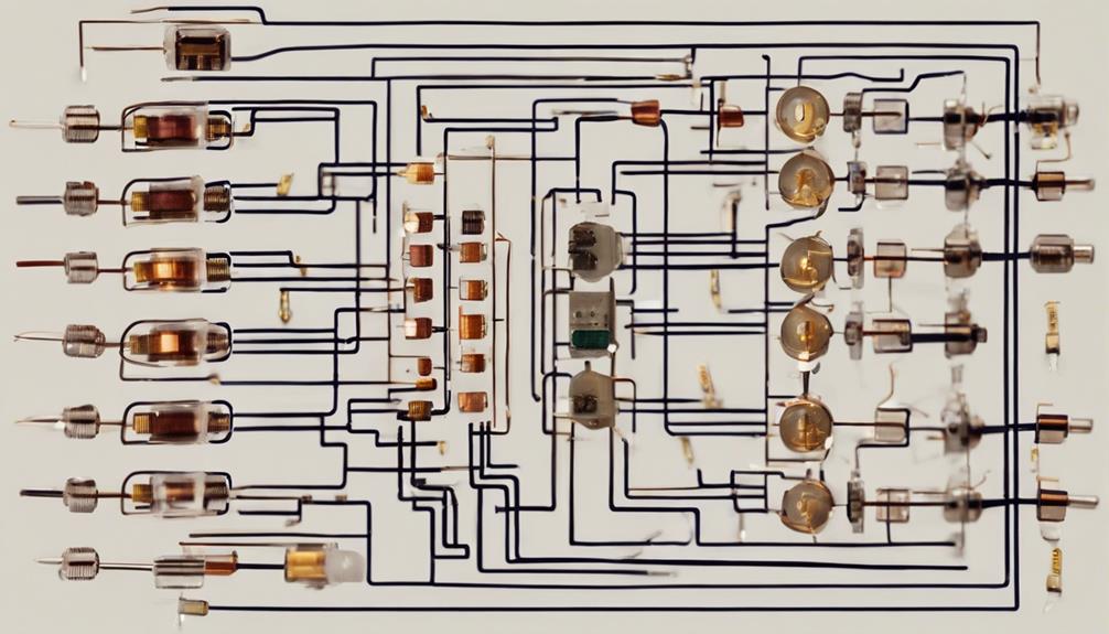
Let’s explore MaxwLet’s inductance bridge circuit diagram, which features a rhombus configuration formed by four arms containing resistors and inductors. The arms labeled bc and cd house resistive components, while the arms ab and ad contain the inductive elements.
The unknown inductor, denoted as ‘L,’ and the variable ‘doctor, ‘ denoted as ‘R,’ are placed strategically to help achieve balance in the bridge. Additionally, the unknown resistance, vital for achieving balance, is labeled as ‘R.’
This setup adjusts an ‘arable resistance ranging from 10 to 1000 ohms’ to achieve the balance conditions. You can accurately determine the unknown inductance value by carefully manipulating the balance point equation.
The circuit diagram’s design allows the diagram to tweak the resistance and inductance values to find the precise balance point. When the bridge is balanced, the unknown inductor and resistance can be accurately determined, proving the efficacy of the Maxwell inductance bridge in measuring inductance and resistance.
Understanding this circuit diagram is essential for effectively utilizing the Maxwell inductance bridge. It lays the foundation for the subsequent calculations and equations to derive precise measurements.
Calculations and Equations
To effectively utilize the Maxwell inductance bridge, you must understand the key calculations and equations determining the unknown inductance and resistance values. The Maxwell bridge is based on balancing the bridge to achieve null deflection, where the current through the meter drops to zero. This null deflection method guarantees accurate measurement of the unknown components.
Calculating the unknown inductance (L3) is straightforward: L3 = R1* R4* C2. R1 and R4 are known resistances, while C2 is a known capacitor. When these values are correctly balanced, the measurement of the unknown inductance becomes reliable and accurate.
The unknown resistance (R3) can also be found using the formula R3 = R1 * R4 / R2. These independent equations allow you to determine both resistance and inductance separately.
In practice, you need a power supply to provide the potential difference across the bridge. The balancing process involves adjusting the resistances and capacitance until the potential difference between the bridge’s arms is zero, the bridge’s null deflection. Understanding these critical calculations ensures you can effectively use the Maxwell inductance bridge for precise measurements.
Advantages

Maxwell inductance bridges excel in their ability to measure high-range inductances accurately and independently of frequency. When you’re working with ACyou’reess, one of the standout features of the Maxwell inductance bridge is its frequency-independent balance equations. This means the accuracy of your measurements won’t fluctuate regarding the frequency at which you’re operating. These are particularly useful for measuring high-range inductances, making them a go-to choice for various applications, especially at audio frequencies. You’ll find thismethoYou’llablee because the balance equations of the Maxwell inductance bridge guarantee consistency and precision in your inductance measurements.
One key advantage is that the balance equations in the Maxwell bridge don’t rely on the free don’t. This frequency-independent balance is a significant benefit, simplifying measuring inductance across different frequencies without recalibration.
Disadvantages
When using the Maxwell inductance bridge, you’ll notice that frequent changes can be a significant drawback.
Additionally, the complex calibration process can make it challenging to achieve accurate measurements.
These issues often lead users to seek alternative methods for more precise inductance evaluations.
Sensitivity to Frequency Changes
Due to variations in impedance at different frequencies, Maxwell inductance bridges can become highly sensitive, potentially leading to inaccurate inductance measurements.
Frequency sensitivity is an important aspect to consider when using a Maxwell inductor capacitance bridge. Changes in AC frequency can cause impedance variations, directly impacting your bridge’s balance condition sensitivity and creating challenges in maintaining accurate and reliable inductance calculations.
Frequency-dependent components in the bridge circuit can further complicate the measurement process. As the frequency shifts, these components may react differently, leading to errors. Therefore, you must be attentive to the frequency you operate the bridge to ensure precision inductance measurements.
Consider these potential issues:
- Balance Condition Shift: Changes in AC frequency may cause the balance condition to shift, making it challenging to maintain accuracy.
- Impedance Variations: Different frequencies cause impedance variations, leading to measurement inaccuracies.
- Frequency-dependent Components: Components that react differently at various frequencies can affect the reliability of your inductance calculations.
Complex Calibration Process
While frequency sensitivity is vital, using a Maxwell Inductance Bridge requires a complex calibration process. Calibration isn’t just a step; it is a meticulous process requiring precise adjustments of resistors and capacitors. You’ll need to be careful. The system must achieve a delicate balance between inductive and capacitive components, which is essential for accurate inductance measurements.
The complexity of this calibration process can’t be overstated. Can’t Minor inaccuracies can lead to significant errors in measuring unknown inductance values. The errors stem from the difficulty of perfectly balancing the bridge. Achieving this balance is critical, as any imbalance directly impacts the reliability of your measurements.
Moreover, the calibration complexity may limit the practicality of some Maxwell users. Not everyone has the expertise or the patience to fine-tune the system to the required precision. This makes the Maxwell Inductance Bridge less user-friendly than other methods, which offer quicker or simpler calibration processes.
Applications
Leveraging its precision in measuring inductance, the Maxwell Inductance Bridge is essential for applications requiring accurate determination of self-inductance in electrical circuits. This sophisticated tool lets you compare unknown inductance values with standard inductors, ensuring high accuracy. You can achieve precise measurements using balanced bridge configurations, making the Maxwell Inductance Bridge invaluable in electrical engineering.
Here are three main applications where you’ll find theMaxwelyou’llctancee Bridge indispensable:
- Circuit Design and Testing: Whether designing new recall circuits or testing existing ones, the bridge helps you measure self-inductance with exceptional precision, ensuring your components meet the required specifications.
- Quality Control in Manufacturing: The Maxwell Inductance Bridge provides a reliable method for quality control in manufacturing environments, especially for inductive components like coils and transformers. It ensures that products meet stringent standards.
- Educational Laboratories: The bridge is an excellent tool for electrical engineering students and researchers. It helps them understand inductance measurement concepts and the practical application of balanced bridge configurations.
Using a Maxwell Inductance Bridge guarantees that your inductance measurements are accurate and reliable, making it a cornerstone tool in various electrical engineering applications.
Related Terminology
Understanding the related terminology that underpins the Maxwell Inductance Bridge‘s functionality and operation is important for fully grasping its applications.
The Maxwell Inductance Bridge, also known as the Maxwell-Swein Bridge or the Maxwell-Sfied Wheatstone Bridge, is designed to compare unknown inductance values with standard values. It achieves this comparison by using calibrated capacitances and resistances.
Understanding frequency independence is essential, as the Maxwell inductance bridge is particularly effective for measuring inductors at audio frequencies without being affected by frequency variations. However, you’ll often need stan you’ll variable capacitors for precise measurements, making the setup more costly.
Another important term is Hays bridge, an alternative setup preferred for advanced inductance measurements, especially when dealing with low-quality coils.
Unlike the Maxwell bridge, the Hays bridge can provide more accurate results for these lower-quality components.
Conclusion
The Maxwell inductance bridge is a game-changer for precise inductance measurement. You can achieve highly accurate results by balancing unknown inductors with known capacitance and resistance.
Its frequency-independent nature and reliability at audio frequencies make it invaluable in circuit design, quality control, and educational labs.
While it has some drawbacks, its advantages far outweigh them, making it an essential tool for anyone needing precise inductance measurements. You’ll find it in various scientific and engineering applications.
FAQs
What is a Maxwell Inductance Bridge?
A Maxwell inductive bridge is an electrical circuit used to measure the inductance of an unknown inductor by balancing the bridge with known resistances and inductances. It is named after James Clerk Maxwell, who contributed significantly to electromagnetism.
How does a Maxwell Inductance Bridge work?
A Maxwell Inductance Bridge operates on the principle of balancing two branches of a bridge circuit. Here is how it works: Here’sConfiguration
- n: The bridge consists of four arms, each containing an electrical component: two known resistances, one known inductance with resistance, and an unknown inductance with resistance.
- Balancing the Bridge: An AC source is applied across the bridge, and adjustments are made to balance the voltage. When balanced, the ratio of the impedances in one branch is equal to the ratio in the other.
- Measurement: By adjusting the known components until the bridge is balanced, the unknown inductance can be calculated using the known values and the balance equation.
What are the key components of a Maxwell Inductance Bridge?
The key components of a Maxwell Inductance Bridge include:
- R1: Known resistance in series with a known inductance (L1).
- R2: Known resistance.
- R3: Known variable resistance for balancing the bridge.
- R4 + jωLx: Unknown inductance (Lx) and its associated resistance (R4).
- AC Source: Provides the alternating current needed for bridge operation.
- Detector: Typically a galvanometer or a sensitive AC voltmeter to detect the balance condition.
What are the applications of the Maxwell Inductance Bridge?
The Maxwell Inductance Bridge is used in various applications, including:
- Measurement of Inductance: Precisely measuring the inductance of coils and inductors in electrical circuits.
- Quality Control: Ensuring the accuracy and quality of inductive components in manufacturing processes.
- Educational Purposes: Teaching principles of AC bridge circuits and electromagnetic theory in academic institutions.
- Calibration: Calibrating other measuring instruments by providing precise inductance measurements.
What are the advantages of using a Maxwell Inductance Bridge?
The advantages of using a Maxwell Inductance Bridge include:
- Accuracy: Provides accurate measurements of inductance and resistance.
- Simplicity: The bridge circuit is relatively simple to set up and use.
- Versatility: Can measure a wide range of inductance values by adjusting the known components.
- Cost-Effective: Often more cost-effective compared to other advanced measuring instruments.
What are the limitations of a Maxwell Inductance Bridge?
The limitations of a Maxwell Inductance Bridge include the following:
- Frequency Dependence: Measurements can be affected by the frequency of the AC source, requiring careful calibration.
- Sensitivity to External Factors: External factors such as temperature and electromagnetic interference can affect the accuracy of measurements.
- Complexity in High-Frequency Applications: The bridge may become less effective and more challenging to balance at high frequencies.
Understanding the principles, components, and applications of the Maxwell Inductance Bridge can help accurately measure inductance and resistance in various electrical and electronic applications.
