

Stators – Functions, Types, and Applications in Motors
Stators play a vital role in the operation of electric machines, such as generators and motors, by providing a stationary magnetic field that interacts with the rotor’s rotating magnetic field. However, stators are susceptible to faults that can hinder their performance and lead to costly downtime. One significant fault that threatens stator integrity is inter-turn faults, which occur when insulation between the individual turns of the stator windings deteriorates or fails. Inter-turn faults can result in short circuits, unbalanced currents, and excessive heating, jeopardizing the overall reliability and efficiency of the machine. Consequently, safeguarding stators from inter-turn faults has become a crucial concern for the industry.
Key Takeaways
- Stator Importance: Stators are crucial components in electric machines, providing a stationary magnetic field that interacts with the rotor.
- Inter-turn faults occur due to insulation failure between stator windings, leading to short circuits and unbalanced currents. Detection requires transverse differential relays for multi-coil stators.
- Ground Fault Protection: Ground faults in stators can be mitigated by restricted ground fault protection, which protects up to 85% of the winding.
- Technological Advances: Continuous improvements in protection systems are vital to ensure the reliability and longevity of electrical systems.
Interturn Fault Protection of Stator
The percentage differential protection relay, also known as a modified Mérz-Pricedifferential relay, cannot sense a turn-to-turn or inter-turn fault on the same phase winding of the stator. This is because the current that these defects produce flows in a local circuit between the turns involved and does not create a difference between the currents entering and leaving the winding at its two ends, where the C.T.s and aC.T.s are sacrificed.
If the stator has only one coil per slot, inter-turn faults cannot occur. However, for multi-coils per slot, inter-turn defects are likely to occur.
Hence, the transverse differential relay detects the stator inter-turn fault, rather than a longitudinal differential relay.
In a multi-coil wound stator, as used in hydro generators, each phase winding is divided into two halves owing to the high currents it must carry.

Parallel Wound Generator
The schematic diagram of a biased transverse differential protection for stator inter-turn faults is shown in the figure above.
A generator with a single winding per phase has an inaccessible parallel winding.

Restricted Ground Fault Protection
If the generator neutral is solidly earthed or grounded, it can protect complete windings against a phase-to-ground fault.
As neutral is earthed through a resistance to limit the earth fault current, with this type of earthing, it is impossible to protect the complete winding from earth fault, and the percentage of winding covered depends upon the value of the neutral earthing resistor and the relay setting. The setting should be such that the protection does not operate for earth faults on the EHV side. Earth faults are less likely to occur near the neutral point due to the lower voltage concern associated with the Earth. The usual practice is to protect about 80 to 85% of the generator winding against earth faults. The differential relay leaves the remaining 20 to 15% winding from the neutral side unprotected. Hence, a separate earth fault protection is provided for the complete winding against earth faults.

During an earth fault in the generator winding (G.W.)G.W.W. mark current IF flows through a part of the winding and is neutral to the ground circuit. The corresponding secondary current I.S. through the operating coil (O.C.)O.C.C., he restricted earth fault (R.E.FR.E.F.F. The coil of differential protection is shown in the figure above.
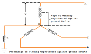
If the earth fault IF occurs at point F of the generator winding, VaF can drive the earth fault current IF through the neutral-to-ground connection. If point ‘F’ is nearer to a, i.e., closer to the neutral point, the forcing voltage VaF is relatively less. Hence, the earth fault current IF will be small. Keeping the relay setting too sensitive to sense the Earth’s fault currents of small magnitudes is impossible. Hence, the practice is to protect approximately 85% of the generator winding against phase-to-earth faults and to leave the remaining 5% portion unprotected by the differential protection against earth faults.
Conculsion
Implementing inter-turn fault and restricted ground fault protection systems is vital for safeguarding the integrity and longevity of stators. Through meticulous monitoring and timely intervention, these advanced defenses shield the heart of electrical systems, preventing potential breakdowns and catastrophic failures. By fortifying stations against internal threats, we ensure uninterrupted power supply and enhance the overall reliability of the electrical infrastructure. As technology advances, it’s crucial to stay dedicated to exploring new ways to protect stators, introducing innovative solutions, and promoting the resilience of these vital components. With the combined efforts of engineers, researchers, and industry professionals, we can forge a future where stators thrive in adversity, delivering consistent performance and powering our world with unwavering reliability.
FAQs
1. What is a stator, and what is its function in an electric motor?
A stator is the stationary part of an electric motor or generator. Its primary function is to generate a magnetic field that interacts with the rotating part (rotor) to produce motion or electricity. In a motor, the stator provides the necessary magnetic field to induce rotor movement, while in a generator, it helps convert mechanical energy into electrical energy.
2. What are the different types of stators used in electric motors?
There are several types of stators used in electric motors, including:
- Synchronous Motor Stators: These stators generate a constant magnetic field that interacts with the rotor to produce synchronized motion in synchronous motors.
- Induction Motor Stators: Found in induction motors, these stators produce a rotating magnetic field that induces current in the rotor, causing it to spin.
- Brushless DC Motor Stators: These stators feature coils arranged in a specific pattern to interact with the rotor’s permanent magnets, enabling efficient and precise control of motor speed and position.
3. How do stators contribute to the efficiency of electric motors?
Stators play a crucial role in the efficiency of electric motors by:
- Optimizing Magnetic Field Production: Well-designed stators ensure efficient generation and maintenance of the magnetic field, reducing energy losses.
- Minimizing Heat Generation: Efficient stators reduce resistive losses, thereby minimizing heat production and improving overall motor performance.
- Enhancing Power Output: By maintaining a strong and consistent magnetic field, stators help maximize the motor’s power output, resulting in improved performance and reliability.
Understanding the role and types of stators can help you appreciate their importance in electric motors and generators, ensuring efficient and reliable operation in various applications.
