

A Journey into Equivalent Circuit of Three-Phase Induction Motor
Basics of Three-Phase Induction Motors
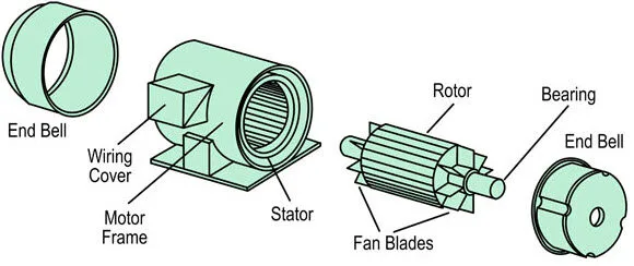
Before immersing ourselves in the equivalent circuit, let’s revisit the foundational principles of three-phase induction motors. These motors leverage electromagnetic induction, creating a rotating magnetic field through three-phase currents in the stator windings.
The behavior of current through series combinations and across nodes provides a strong example of how charge distribution is affected by frequency, capacitance, and overall network configuration. These characteristics form the basis of understanding both linear and nonlinear electrical properties.
Understanding the Equivalent Circuit
The equivalent circuit of a three-phase induction motor is a valuable model that simplifies the analysis of the motor’s electrical characteristics. It enables engineers to predict the motor’s behavior under different operating conditions without delving into the intricacies of its construction.
Equivalent circuits allow for the representation of both linear and nonlinear components, such as diodes, batteries, and capacitors. These models are valuable in simulation platforms, helping analyze systems with different input and output signals across a range of frequencies.
Components of the Equivalent Circuit
Stator and rotor circuits in a three-phase induction motor involve key elements such as voltage, Electromotive forces (Fs), resistances, and reactances, which determine the electrical characteristics.
Stator Circuit

In the stator winding, the actions mirror those in the primary winding of a transformer. The applied voltage per phase (V1) induces self-induced EMF (E1) in the stator winding and mutually induced EMF (E2′) in the rotor winding. The stator circuit equation is given by:
V1=−E1+I1(R1+jX1)
At no load, the stator windings draw current I0=Iw+Im, where
Stator Winding Resistance (Rs)
The stator winding resistance represents the resistive losses within the stator windings when current passes through them. This resistance contributes to the copper losses of the motor and is an important factor in determining its efficiency.
Stator Leakage Reactance (Xls)
The stator leakage reactance accounts for the magnetic flux that does not link with the rotor and remains confined within the stator core. This leakage flux does not actively contribute to torque production, resulting in additional reactive losses.
Rotor Circuit
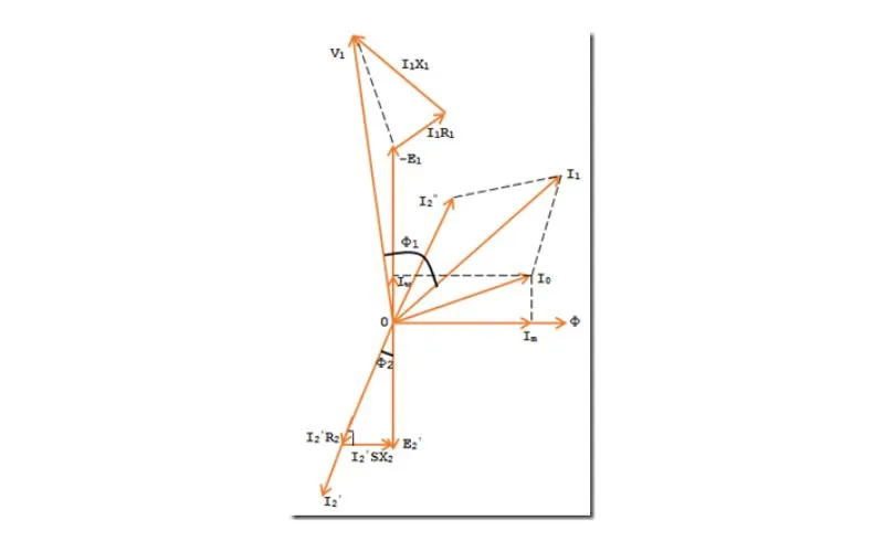
The rotor circuit comprises rotor resistance (), standstill rotor reactance (), and induced voltage per phase in the rotor circuit (E2′=I2′(R2+jSX2)). The rotor current () is reflected as ′′ in the stator, contributing to the overall stator current (). When current flows through the rotor network, the simulation must consider changes in parameters like r3 (resistance), capacitance, and reactance. These influence both the input-output response and the equivalent model representation. The region and function of each rotor component determine its effect on the overall system.
Rotor Winding Resistance (Rr)
Like the stator winding resistance, the rotor winding resistance represents the resistive losses in the windings. These losses result in rotor copper losses, which in turn affect the overall efficiency of the motor.
Rotor Leakage Reactance (Xlr)
The rotor leakage reactance accounts for the portion of the magnetic flux that does not link with the stator and remains confined within the rotor core. This leakage flux influences the rotor’s reactance and efficiency.
Magnetizing Reactance (Xm)
The magnetizing reactance represents the core magnetic flux required to establish the rotating magnetic field in the motor. It plays a vital role in determining the no-load current and is a key factor in calculating the motor’s magnetizing current.
Mechanical Load ()
The mechanical load represents the external resistance connected to the motor, impacting its performance under varying loads.
Circuit Analysis
Resistors and Resistances
- Resistor (R): Represents the opposition to current flow.
- Ohm’s Law: Describes the relationship between voltage, current, and resistance (�=��).
Capacitors and Inductors
- Capacitors: Components that store electrical energy in an electric field.
- Inductors: Elements that store energy in a magnetic field.
DC Circuits and Voltage Sources
- DC Circuits: Circuits with direct current flow.
- Voltage Source: Provides a constant voltage.
Circuit Analysis Tools and Theorems
- Kirchhoff’s Laws: Principles governing current and voltage in circuits.
- KVL (Kirchhoff’s Voltage Law): States that the total voltage in a closed loop equals the sum of the voltages across its elements.
- Norton’s Theorem Simplifies complex circuits by representing them as an equivalent current source and resistor.
- Superposition Theorem: Simplifies circuit analysis by considering the impact of each source individually.
Complex Circuits and Impedance
- Impedance: A circuit’s overall opposition to the flow of alternating current.
- Complex Circuits: Incorporate both resistive and reactive components.
Applications and Importance of Equivalent Circuit Modeling in Electrical Systems
The equivalent circuit model plays a crucial role in both academic learning and real-world electrical engineering applications. Whether you’re working with a three-phase induction motor or analysing the behaviour of complex networks, these simplified representations enable efficient simulation, problem-solving, and system analysis. By breaking down the motor’s architecture into series and parallel branches, engineers can focus on the value, response, and effect of each component without needing to navigate the entire system manually.
In design scenarios, especially when working with online devices like diodes or managing capacitive loads, this model facilitates easier visualization of voltage drop, current flows, and signal transfer. The concept of equivalence also facilitates testing under varied frequency and input-output conditions, helping engineers identify potential limitations and optimise performance before implementing it in the real world.
Moreover, these circuit models are widely used in simulation software, allowing students and professionals to run what-if scenarios, assess open-circuit voltage, or understand the consequences of a short circuit. Ultimately, mastering equivalent circuits equips engineers to approach design challenges with clarity, saving time, reducing errors, and enhancing the overall efficiency and functionality of modern electrical devices.
