

Output, Losses and Efficiency of an Induction Motors
In modern electric motor technology, understanding output, losses, and efficiency is crucial for optimizing power supply systems and minimizing thermal losses. Among the array of motors, induction motors emerge as workhorses vital to a diverse range of industries. This article examines how induction motors, including models such as Tesla systems and Variable Frequency Drive (VFD) configurations, operate efficiently across a range of speeds and load levels. This exploration navigates the factors that intricately influence an induction motor’s productivity, the losses it incurs, and the overarching efficiency it delivers. By comprehending these intricate facets, engineers gain the insights to judiciously enhance efficiency and productivity across a spectrum of operational landscapes.
The efficiency of an induction motor depends on several factors, including motor size, number of poles, speed control, and the type of power supply. Technologies like VFD (Variable Frequency Drive) and thermal optimization methods help reduce energy loss and improve performance. Tesla’s early model set the foundation for modern systems. Companies and the engineering community conduct research to enhance standards, meet diverse needs, and address problems at different levels. Proper maintenance, fans, and motion control are crucial for the long-term operation of the system. This information helps select the right motor for your purpose. For example, industrial products often require specific speeds and efficiency percentages to reach their goal.
Induction Motor Efficiency Enhancement
Regarding electrical motors, efficiency is critical. Induction motors are widely used and essential in various industries. This article examines the factors that influence the production, losses, and overall efficiency of an induction motor. By gaining insights into these aspects, engineers can make informed decisions to maximize efficiency and productivity in different operational settings.
The efficiency of an induction motor depends on several factors, including skin depth, resistivity, conductor width, length, number of wire turns, voltage, and ampere rating. Stator losses include stator copper and iron losses, while rotor losses comprise rotor iron and copper losses. Other losses on the rotor side are friction losses at bearings and slip rings, as well as windage losses. Engineers can enhance the efficiency and performance of induction motors by considering and optimizing these factors.
The stator iron losses depend on two factors: flux density and supply frequency. The rotor iron loss depends on the frequency of the rotor current. The rotor current’s frequency depends on the rotor’s slip or speed (f’ = sf). The iron losses of the rotor are negligible since the frequency of the rotor current is very small.
Power stages and various losses in an Induction Motor

Power flow chart of an Induction Motor

-
Rotor copper loss is determined by using the formula 3I22R2.
-
Stator copper loss is calculated by using the formula 3I21R1
-
The input to the motor on load is equal to √3VLIL cos (Φ) watts.
Slip Torque characteristics of an induction Motor
Three-Phase Induction Motor Rotor Output
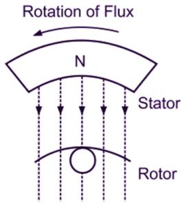
Three-phase induction motors, especially those enhanced with model optimization and advanced VFD systems, offer consistent torque at multiple speed levels. The output available at the rotor shaft is mechanical energy.
During the power conversion process, certain losses occur at various stages. The rotor output of an induction motor is given as follows:
Mechanical Energy —-> Gross Torque Tg
Where Nr = actual speed of the motor in r.p.m
From this Tg = Rotor output in watts / 2πNr ——–> 1
For this condition, the motor should run at synchronous speed.
Tg = Rotor Input / 2πNs ——–> 2
Rotor output = 2πNrTg ——–> 3
Rotor input 2πNsTg ——–> 4
(Rotor input – Rotor output) = Rotor copper losses
Using the eqn 3 & 4
That is Rotor copper losses = Tg. 2π(Ns – Nr) ——–> 5
= Slip S ——–> 6
s x Rotor input ——–> 7
But Rotor Gross Output = Rotor input – Rotor copper losses
= (1-s) Rotor input
Rotor gross output/Rotor input = (1-s) ——–> 8
=Nr/Ns
Rotor efficiency = Nr/Ns
Rotor copper losses/Rotor Gross input = s/(1-s)
The Efficiency of an Induction Motor
Induction motors receive power from the supply mains through their stator windings. The input power is electrical power. The energy from the stator winding is transferred to the rotor via the air gap by the induction principle. The output power is mechanical. The mechanical power is obtained at the motor shaft to perform mechanical work.
During this power transfer, some losses occur, such as copper losses in the stator winding, copper losses in the rotor winding, core losses in the Stator winding, frictional losses, and windage losses.
Efficiency percentages vary based on factors such as input voltage, conductor size, and power supply conditions across motor systems.
The efficiency of any machine is the ratio of output power to input power. The efficiency of induction motors is obtained as
Smart Technologies for Increasing Induction Motor Efficiency
Modern motor monitoring and control technologies have revolutionized the way engineers enhance the efficiency of induction motors. They improve performance, enable predictive maintenance & reduce downtime. Here’s how:
1. Variable Frequency Drives (VFDs)
- Control the motor speed based on load requirements.
- Reduce starting currents and energy consumption in light-load conditions.
- Enhance torque control and extend motor lifespan.
2. Smart Sensors and IoT Integration
- Monitor parameters like temperature, vibration, and current in real-time.
- Enable predictive maintenance by detecting issues before failure.
- Connected motors can communicate with central systems for automated optimization.
3. Artificial Intelligence and Machine Learning
- AI algorithms analyze motor performance data for deeper insights.
- Can predict optimal operating conditions and suggest design tweaks.
- Helps identify efficiency bottlenecks in large-scale industrial settings.
4. Digital Twins and Simulation
- Digital replicas of motors simulate various load scenarios.
- Allows virtual testing of design changes or environmental factors.
- Improves motor design without physical prototyping.
5. Energy Management Systems (EMS)
- Integrates motors into broader energy optimization platforms.
- Tracks and reports efficiency metrics across a facility.
- Supports compliance with green building standards and energy certifications.
Conclusion
In conclusion, understanding the output, losses, and efficiency of induction motors is crucial for maximizing their performance and optimizing energy usage. By comprehending the factors that influence motor output, such as voltage, frequency, and rotor design, engineers can design and operate induction motors to meet specific application requirements. Additionally, being aware of the different types of losses, including copper, iron, and mechanical losses, allows for the identification and mitigation of inefficiencies within the motor system. Ultimately, striving for high motor efficiency reduces energy consumption, minimizes operating costs, and mitigates environmental impact. Continuous advancements in motor design, control techniques, and the adoption of energy-efficient practices contribute to a sustainable and greener future. With a thorough understanding of induction motors’ output, losses, and efficiency, engineers can make informed decisions, optimize motor performance, and contribute to a more energy-conscious world.
Related Article
(FAQs)
What is the rotor copper loss formula in a DC motor?
The rotor copper loss formula calculates the power dissipated as heat in the rotor due to the resistance of the copper windings. It can be calculated using the formula Rotor Copper Loss = (I^2) * R, where I represents the current flowing through the rotor windings and R represents the resistance of the rotor windings.
How does the rotor copper loss affect the overall performance of a DC motor?
Rotor copper loss contributes to the total power losses in a DC motor, which reduces its efficiency. Higher rotor copper losses lead to increased heat generation, which can negatively impact the motor’s performance, efficiency, and lifespan.
Can the rotor copper loss be minimized in a DC motor?
While the resistance of the rotor windings determines the copper loss, it is usually a fixed value for a given motor. However, by using materials with lower resistance or optimizing the motor design, it is possible to reduce the rotor copper loss and improve the overall efficiency of the motor.
How can the rotor copper loss be determined experimentally?
The rotor copper loss can be determined experimentally by measuring the current flowing through the rotor windings and the resistance of the rotor windings. Using these values in the rotor copper loss formula allows for the calculation of the power dissipated as heat in the rotor.
Are there any practical considerations for reducing rotor copper losses in DC motors?
Yes, there are several practical considerations. These include using materials with lower resistivity for the rotor windings, ensuring proper cooling and ventilation to dissipate heat effectively, and employing efficient motor designs that minimize resistive losses. Maintaining appropriate operating conditions and avoiding excessive overloading can also help reduce rotor copper losses in DC motors.
