

DOL Starter Control Circuit Diagram | Working, Components
When examining a DOL starter control circuit diagram, you’re not just looking at lines and symbols; you’re uncovering the blueprint that guarantees an electric motor’s efficient and safe operation. This diagram is more than a mere technical drawing; it’s a guide that highlights critical components like the magnetic contactor and overload relay, which work seamlessly to protect your motor from overload. As you trace the current path from the power source through the start and stop buttons, you might wonder how each element contributes to the system’s reliability. What happens when something goes wrong?
Key Takeaways
- A DOL starter control circuit diagram shows connections for the R, Y, and B power supply phases power supply phases.
- It includes components like a magnetic contactor, overload relay, and circuit breaker/fuse.
- The diagram illustrates the start (green) and stop (red) button wiring for safe motor operation.
- It demonstrates the energizing process of the relay coil to activate the motor.
- Overload relay protection is depicted to prevent damage from excessive current.
Understanding DOL Starters
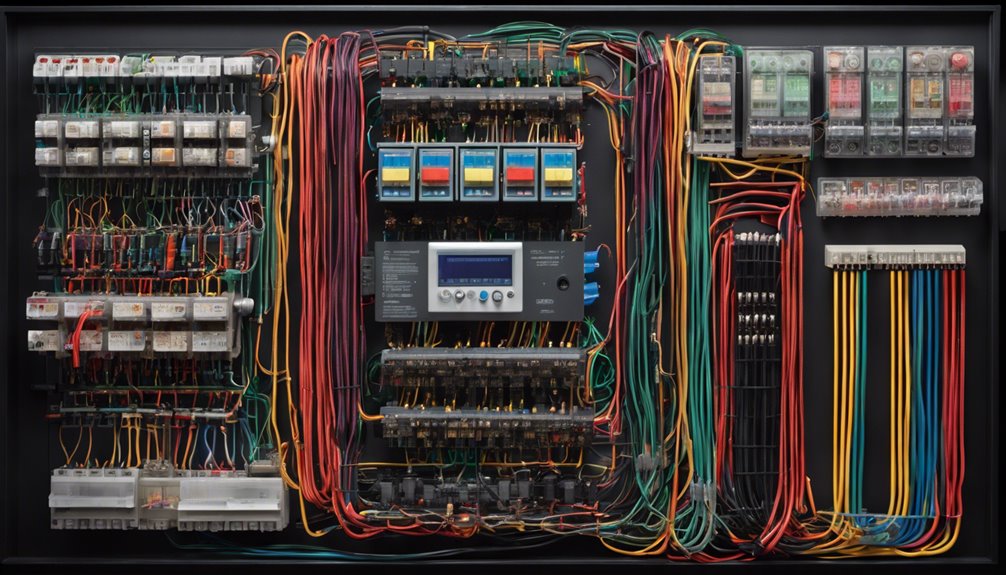
Understanding DOL starters’ fundamental role in motor control is vital to grasping them. A DOL, or Direct-On-Line starter, connects an electric motor to a three-phase power supply. This gives the motor full voltage, enabling high starting torque and immediate operation. This is particularly useful for induction motors up to 5 HP, often found in small pumps and fans.
The DOL starter relies primarily on two significant components: the magnetic contactor and the overload relay. When you press the start button, the magnetic contactor is energized. This action allows the full voltage to flow to the motor, effectively starting it.
However, motors are susceptible to damage from excessive current. That’s where the overload relay comes into play. It continuously monitors the motor’s current, and if it detects an overload, it trips, disconnecting the motor from the power supply to prevent damage.
The DOL starter guarantees efficient motor operation while safeguarding against electrical faults. Understanding this system is vital for anyone working with motor applications, as it guarantees functionality and safety.
Essential Components
At the heart of a DOL starter system are its essential components, each playing an important role in motor control and protection. You’ll find that these components are indispensable for guaranteeing the motor operates efficiently and safely.
A magnetic contactor is one of the key elements, acting as an electrically operated switch. It controls the power supply to the motor, engaging and disengaging the current as needed.
Another significant component is the overload relay. It constantly monitors the current flowing through the motor. If the current exceeds safe limits, the relay trips, disconnecting the motor from the power supply to prevent damage. This safeguard is essential for maintaining the longevity of your equipment.
Additionally, a circuit breaker or fuse plays a significant role in the DOL starter system. It protects the entire setup from short circuits and overloads by interrupting the current flow when necessary, maintaining the system’s integrity, and preventing potential hazards.
Here’s a quick rundown of these components:
- Magnetic Contactor: Controls the power supply to the motor.
- Overload Relay: Monitors and protects against excessive current.
- Circuit Breaker/Fuse: Protects from short circuits and overloads.
Wiring Diagram Overview

A well-constructed wiring diagram is essential for understanding and implementing a DOL starter circuit. It provides a clear layout of connections for the three-phase power supply (R, Y, B) to the motor, ensuring you can efficiently manage the current draw.
The power circuit contains a circuit breaker and a magnetic contactor. These components are crucial for controlling the power supply to the motor, allowing you to start and stop the motor as needed.
The start button (usually green) in the control circuit is wired with the magnetic contactor coil, while the stop button (red) is also in series. This allows you to operate the motor safely.
The wiring diagram shows auxiliary contacts on the magnetic contactor, which form a holding circuit. This design keeps the contactor energized even after you release the start button.
To protect the motor, the overload relay is connected in series. It constantly monitors the current draw and trips the circuit if the current exceeds safe limits, preventing motor damage.
Clear labeling in the diagram is crucial for accurate installation and troubleshooting, ensuring everything works correctly.
Protection Mechanisms
Many essential protection mechanisms in a DOL starter circuit ensure the motor’s safety and longevity. One key component is overcurrent protection, which significantly prevents damage to the motor. This feature interrupts the current flow whenever a short circuit occurs, safeguarding the motor and the entire electrical system.
A circuit breaker or fuse is integral to this process, as it quickly disconnects power during overcurrent conditions, ensuring safety and preventing costly equipment damage.
Another critical protection mechanism is the overload relay. This device continuously monitors the current drawn by the motor. If the current surpasses predetermined safe limits, the overload relay will trip the circuit, preventing overheating and potential motor failure.
Different overload relays, such as thermal, magnetic, and electronic, offer varied response times and sensitivities to overload conditions.
Here’s a quick rundown of these protection mechanisms:
- Overcurrent protection: Interrupts current flow during short circuits.
- Circuit breaker or fuse: Disconnects power quickly during overcurrent.
- Overload relay: Monitors and trips the circuit to avoid overheating.
Integrating these mechanisms properly is essential for maintaining motor reliability and extending its operational lifespan.
Operational Process
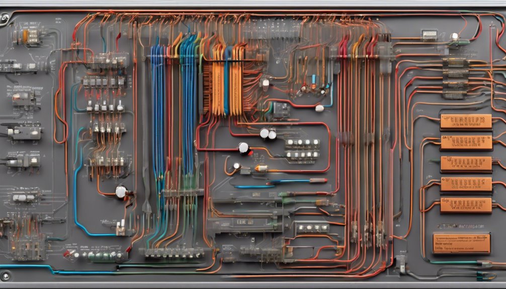
Understanding the operational process of a DOL starter is essential for guaranteeing efficient motor control. Pressing the start button energizes the relay coil, which closes the contactor and connects the motor to the power supply. At this moment, the motor receives full voltage, enabling it to start immediately at maximum torque. This swift startup requires 5-6 times the motor’s rated current. The immediate availability of full power guarantees that the motor functions at its peak capacity right from the start.
The operational process includes monitoring mechanisms to safeguard the motor. The overload relay plays a pivotal role by continuously monitoring the motor current. If this current exceeds a preset limit, the relay trips the circuit, cutting off the power supply. This action protects your motor from potential damage due to excessive current flow.
To stop the motor, press the stop button. This de-energizes the relay coil, opens the contactor, and swiftly halts the motor’s operation swiftly.
Meanwhile, auxiliary contacts in the circuit guarantee the motor remains powered until either the stop button is pressed or an overload condition prompts a shutdown, maintaining operational reliability.
Features and Benefits
The DOL starter control circuit diagram simplifies motor control, making it easy to understand and implement.
This straightforward setup streamlines operation and serves as a cost-effective solution for motor management.
Simplified Motor Control
A simplified motor control circuit using a Direct-On-Line (DOL) starter offers distinct features and benefits that enhance safety and efficiency. By incorporating a DOL starter, you can directly apply full voltage to the motor, which delivers 100% starting torque. This is vital for applications where immediate motor engagement is necessary.
An overload relay in the circuit protects the motor from overheating and potential damage. It trips the power supply if the current exceeds safe limits, adding a layer of safety to your operations.
When you opt for this simplified setup, you’re embracing a system designed for ease of use and reliability. Here’s what you can expect:
- Efficiency and Reliability: It is ideal for small motors up to 5 HP, commonly used in various industrial and commercial settings.
- Quick Troubleshooting: Simplified circuits mean faster maintenance and reduced downtime, enhancing overall operational efficiency.
- Enhanced Safety: With start and stop buttons, a contactor, and an overload relay, operation becomes straightforward and secure.
Utilizing a simplified motor control circuit boosts efficiency and prioritizes safety, making it a smart choice for many applications.
Cost-Effective Solution
The DOL starter stands out for its simplicity and efficiency when looking for a cost-effective solution. It provides a straightforward and economical method of kickstarting motors, especially those under 5 HP, by directly connecting an induction motor to the full voltage supply.
Its uncomplicated design minimizes installation space and reduces associated costs, making it the go-to choice for various industrial applications.
The DOL starter’s control circuit is as simple as it gets. It incorporates a contactor, an overload relay, and basic start/stop buttons. This simplicity makes operation and maintenance a breeze and guarantees reliable performance with minimal downtime.
You’ll appreciate the 100% starting torque available from the start, making it highly effective for applications requiring maximum starting power, such as small pumps and fans.
Opting for a DOL starter means investing in a solution that eliminates the complexity and cost of advanced control systems. This approach keeps project expenses in check while delivering dependable motor operation.
The DOL starter is your best bet when you need effective motor control without breaking the bank.
Limitations of DOL Starters
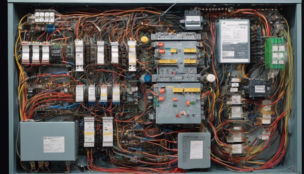
The high inrush currents produced by DOL starters can significantly stress the motor and supply network.
This can lead to voltage drops, disrupting other connected electrical appliances.
Considering these impacts is vital, especially in systems where consistent voltage levels are essential.
High Starting Current Impact
One significant limitation of Direct-On-Line (DOL) starters is the high starting current they draw, often 5-6 times the motor’s rated current.
This inrush current can be problematic, as it subjects the motor windings to excessive current, leading to potential damage or failure. Although DOL starters offer simplicity and reliability, they don’t inherently protect the motor from these high currents, which can compromise its longevity.
The impact of a high starting current isn’t limited to the motor itself. It can cause line voltage dips, affecting other electrical devices on the same circuit.
This issue can lead to unexpected shutdowns or malfunctions in your equipment. Additionally, the mechanical stress caused by the 100% starting torque can strain both the motor and the connected load, potentially reducing their operational lifespan.
Here are a few challenges you might face with DOL starters:
- Increased mechanical stress: Full torque at startup can wear down components faster.
- Additional circuit protection: Extra equipment may be needed to manage excessive current, increasing complexity and cost.
- DOL starters are unsuitable for soft-start applications, such as systems that need applications and a gentle startup to prevent damage.
Voltage Drop Concerns
Addressing the high starting current of Direct-On-Line (DOL) starters naturally leads to examining voltage drop concerns. When a motor begins operating, the high current inrush—often 5-6 times the motor’s rated current—can cause significant voltage drops. This drop occurs because the sudden surge in motor current demands more from the electrical supply than it can smoothly deliver, especially if the system has long cable runs. The increased resistance in these cables exacerbates the voltage drop, making it more pronounced and problematic.
These voltage dips can affect more than just the motor in an industrial setting. Other equipment connected to the same power supply might experience disruptions or damage, particularly those with sensitive electronics.
Furthermore, other motors or devices could suffer poor performance due to fluctuating voltage levels, which might require you to explore alternative starting methods for larger motors. Continuous voltage drops decrease equipment efficiency, increase energy consumption, and reduce system reliability.
To mitigate these issues, evaluate your system’s layout and assess the impact of high current on voltage drop. This will guarantee the motor and connected equipment’s ideal performance and longevity.
Common Applications
DOL starters excel in various industrial and commercial settings, making them essential components and applications. A Direct Online Starter is perfect for small water pumps requiring immediate starting power without complex control systems. A DOL starter with a three-phase motor protects by efficiently handling the high inrush current, making it ideal for applications where simplicity and reliability are key.
Consider these common uses:
- Conveyor Belts: High starting torque is essential for smooth operation, especially when moving heavy loads. DOL starters guarantee that conveyor belts start efficiently and run smoothly.
- Industrial Fans: These require efficient airflow and full voltage application during startup. Using a DOL starter minimizes lag and maintains consistent performance for your fans.
- Compressors: Overcoming the initial resistance in compressed air systems demands a high starting torque, which DOL starters are well-equipped to provide.
DOL starters are generally best suited for motors with power ratings up to 5 HP. They’re effective in scenarios where the high inrush current doesn’t negatively impact the power supply, offering a simple yet robust solution for your motor control needs.
Troubleshooting Tips

When troubleshooting DOL starter issues, check the power supply to verify the circuit breaker, or fuse hasn’t tripped or blown—this can quickly halt the starter’s operation.
Next, confirm that all connections are tight and free from damage. Loose or broken wires can cause intermittent operation or failure to start.
Inspect the start button closely. A malfunctioning start button might be why your motor isn’t kicking off as it should.
Also, remember the stop button; if it’s faulty, it may not properly disconnect the motor, leading to potential problems.
Pay close attention to the overload relay settings, which should match the motor’s rated current. Incorrect settings can cause unnecessary tripping and disrupt the motor’s operation.
The relay monitors the current and protects against overloads, so it’s essential to set it correctly.
A multimeter measures the voltage across the contactor terminals when the start button is pressed to identify issues within the control circuit.
If there’s no voltage, you might be dealing with a problem in the control circuit, possibly due to short circuits or other faults.
Address these promptly to confirm the smooth operation.
Conclusion
By understanding a DOL starter control circuit diagram, you’ll understand how to operate and protect an electric motor effectively. The diagram’s layout simplifies the process, guaranteeing proper connections and safe motor functioning. While DOL starters offer straightforward and cost-effective solutions, remember their limitations in handling large motors. Familiarize yourself with troubleshooting tips to maintain efficiency. With this knowledge, you can guarantee reliable motor performance across various applications.
FAQs
1. What Is a DOL Control Circuit?
A DOL control circuit uses contactors and overload relays to start motors at full voltage. Its simplicity and cost-effectiveness advantages make it suitable for DOL applications involving small motors with straightforward operation needs.
2. What Is the Control Circuit of a Starter?
You’re wondering about starter control circuits. They include various starter types, control components like start/stop buttons, and guarantee circuit safety. They manage the motor operation, maintain power, and protect against overloads, keeping everything running smoothly and securely.
3. How Does a Dol Starter Work?
You push the start button, energizing the contactor, and the DOL starter connects the motor directly to power. It guarantees efficiency and motor protection by using an overload relay to trip the circuit if the current exceeds safe limits.
4. How do you connect the Dol Starter Single-Phase?
To connect a single-phase DOL starter, guarantee safety first. Use single-phase wiring and connect DOL starter components like the circuit breaker, magnetic contactor, and overload relay. Integrate a motor protection circuit for safe operation to prevent damage.
