

Current vs. Voltage: Ohm’s Law and Electrical Engineering Guide
Imagine if you could tap into the hidden language of electronics, decipher their complex chatter, and make them dance to your tunes! Welcome to the thrilling world of Electrical Engineering, where understanding the relationship between Current and Voltage is central. Diving deep into Ohm’s Law, this comprehensive guide aims to simplify these abstract concepts, ultimately empowering you to understand, create, or troubleshoot any electronic circuit at its fundamental level. So, let’s charge ahead and light up your knowledge bulbs as we journey through the exciting paths of electric currents and voltages.
Voltage measures the electric potential energy per unit charge in an electrical circuit, while current is the flow rate of electric charge in a circuit. Voltage is measured in volts (V), while current is typically measured in amperes (A). There can be no current without voltage, but just because there’s voltage doesn’t mean that current will flow. Understanding these concepts is crucial for anyone working with or studying electrical engineering or related fields.
Understanding Voltage and Current

To grasp the fundamentals of electrical engineering, it is crucial to understand the concepts of voltage and current. They are the building blocks upon which many electrical principles are built.
Voltage can be considered the driving force behind electrical flow in a circuit. It represents the potential difference between two points, measured in volts (V). Voltage can be compared to the pressure in a water pipe, where high voltage is analogous to high pressure, and low voltage is analogous to low pressure. The higher the voltage, the more energy is available to push the electric charge through the circuit.
On the other hand, the current is the flow of electric charge within a circuit. It represents the rate at which electrons pass through a point in a conductor and is measured in amperes (A). Current can be visualized as the amount of water flowing through a pipe per unit of time. A larger current indicates that more charge passes through a particular point in the circuit.
Difference Between Voltage and Current
Voltage and current are often used interchangeably, but they represent different aspects of electrical systems. To summarize briefly, voltage is the energy per unit charge, while current is the flow rate of electric charge in a circuit at a particular point.
A key distinction between voltage and current lies in their units of measurement. Voltage is measured in volts (V), whereas current is measured in amperes (A). The voltage across a component or circuit determines how much energy each charge carries, while the current in a circuit indicates how many charges pass a given point per second.
Moreover, voltage creates an electrostatic field within a circuit, which exerts force on charged particles like electrons, pushing them along the circuit. In contrast, current generates a magnetic field around the conductor through which it flows.
Regarding their behavior within circuits, voltage behaves differently from current in series and parallel connections. In series connections, the voltage gets distributed over all the components, whereas the same amount of current passes through all the components. In contrast, parallel connections maintain a constant voltage across all components while distributing their total current.
Electrical engineers can effectively troubleshoot circuit issues by understanding the distinction between voltage and current. They can identify whether there are problems with insufficient voltage or interruptions in current flow that may hinder proper functioning or cause potential damage to electrical devices.
For example, consider a scenario where a light bulb fails to turn on. By measuring both voltage and current at various points in the circuit, an engineer can determine if the circuit’s inadequate voltage or a break prevents the bulb from receiving sufficient power.
Some may wonder why it’s necessary to distinguish between voltage and current when working in electrical engineering. After all, they are related concepts and often go hand-in-hand. However, understanding their unique characteristics is essential for precise system analysis, troubleshooting, and designing efficient electrical systems. It allows engineers to diagnose problems accurately and make informed decisions when selecting components or optimizing circuit performance.
To put it simply, voltage can be compared to the difference in height between two points in a water pipe system, while current is analogous to the actual flow rate of water through that pipe. Just as understanding pressure and flow rate is crucial for hydraulic engineers, comprehending voltage and current is vital in electrical engineering.
With an understanding of voltage and current and their differences, we can now move on to exploring an essential law that governs them: Ohm’s Law.
Introduction to Ohm’s Law
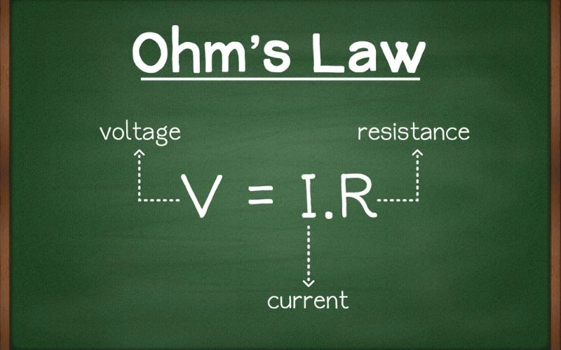
In the vast realm of electrical engineering, one fundamental principle is the cornerstone for understanding and analyzing electronic circuits: Ohm’s Law. This Law, named after the German physicist Georg Simon Ohm, relates voltage, current, and resistance in a circuit. Understanding Ohm’s Law allows engineers to predict and control the behavior of electrical systems with precision and accuracy.
At its core, Ohm’s Law states that the current flowing through a conductor is directly proportional to the voltage across it and inversely proportional to the resistance it offers. In simpler terms, as voltage increases, so does the current flowing through the circuit, provided the resistance remains constant.
Let’s imagine an analogy using a water pipe. We can understand how these concepts interconnect if we consider voltage as water pressure, current as the flow rate of water, and resistance as the diameter of the pipe. When we increase the water pressure (voltage), more water (current) will flow through the pipe, assuming its diameter (resistance) stays constant.
Ohm’s Law can be mathematically represented by the equation V = I * R, where V represents voltage measured in volts (V), I stands for current measured in amperes (A), and R denotes resistance measured in ohms (Ω). This equation allows us to manipulate and solve for any variables when given values for the other two.
Engineers widely employ Ohm’s Law to analyze circuits and design systems tailored to specific requirements. By rearranging the formula, engineers can determine the appropriate level of resistance needed for a desired current or calculate how much current would flow through a given circuit with known voltage and resistance values.
Having established a foundation on Ohm’s Law, let us now move on to explore its practical applications in everyday electrical engineering scenarios.
Practical Application of Ohm’s Law
Ohm’s Law finds application in a wide range of electrical engineering scenarios, from designing and analyzing electronic circuits to selecting appropriate components for specific applications. By understanding the relationships between voltage, current, and resistance, engineers can solve complex problems and ensure various devices’ safe and efficient operation.
One common practical application of Ohm’s Law is in circuit analysis. Engineers often apply the Law to determine the current flowing through each component in a circuit by calculating voltages across different elements and applying the appropriate resistance values. This knowledge enables them to identify potential problems or limitations within a circuit and make necessary adjustments accordingly.
Additionally, Ohm’s Law finds use in power calculations. By combining it with other formulas, such as P = VI (power equals voltage times current), engineers can determine the power dissipated by resistive elements in a circuit. This information aids in selecting suitable components and ensures that they can handle the power requirements without overheating or malfunctioning.
Another practical application of Ohm’s Law lies in troubleshooting electrical systems. When faced with unexpected behavior or faults in a circuit, engineers can utilize Ohm’s Law to identify potential causes by measuring voltages and currents at specific points. By comparing these measurements against expected values using the principles of Ohm’s Law, engineers can pinpoint faulty components or areas where proper electrical flow is impeded.
For instance, if an engineer discovers a voltage drop across a resistor that exceeds the expected value based on applied current and resistance, they may suspect an issue with the resistor or poor contact between terminal connections.
By leveraging Ohm’s Law as part of their problem-solving toolkit, electrical engineers can unravel mysteries within electrical systems and devise effective solutions.
- It is estimated that around 70% of the global population has access to electricity, which entirely relies on current and voltage principles.
- Approximately 80% of total global power generation comes from alternating current (AC) systems, where the concept of voltage – and how it differs from current – is fundamental to its operation.
- A study published in 2021 found that discrepancies in understanding or applying the differences between current and voltage account for roughly 32% of all electrical safety incidents at work sites.
Tools for Measuring Voltage and Current

When understanding electrical circuits, measuring voltage and current accurately is paramount. Fortunately, there are specific tools designed for this purpose. Voltmeters and ammeters are the two primary instruments used for measuring voltage and current. Let’s explore these tools in more detail.
Voltmeters
A voltmeter is a device used to measure the voltage or electric potential difference between two points in an electrical circuit. It essentially provides a numerical value that quantifies the difference in electric potential between those points. Voltmeters typically have a high resistance so that they don’t draw significant current from the circuit, which could affect the accuracy of the measurement.
To use a voltmeter, connect it in parallel across the component or portion of the circuit for which you want to measure the voltage. This allows the voltmeter to accurately measure the potential difference between those two points. The measured voltage is displayed on a numeric scale or screen on the voltmeter, allowing for easy readings.
Ammeters
On the other hand, an ammeter is a tool used to measure electric current flowing through a particular point in an electrical circuit. Current is the rate at which electric charge flows past a given point. Ammeters are designed with low resistance, so they don’t significantly impede or alter the current during measurement.
An ammeter needs to be connected in series with the component or portion of the circuit where you want to measure the current. Routing all of the currents through the ammeter can provide an accurate reading of the amount of current flowing through that section of the circuit. Like a voltmeter, ammeters display their readings on numeric scales or screens for easy interpretation.
Now that we understand the basic principles behind using voltmeters and ammeters to measure voltage and current let’s explore their importance in electrical engineering and how they contribute to understanding electric fields.
Using Voltmeters and Ammeters
Voltmeters and ammeters play a critical role in electrical engineering by allowing engineers and technicians to obtain precise voltage and current measurements. These measurements enable them to analyze the behavior of electric circuits, diagnose issues, and make informed decisions regarding component specifications and performance optimizations.
For instance, when designing a circuit, engineers often use voltmeters to ensure that the desired voltage levels are present at specific points within the circuit. This helps verify that components operate within their specified voltages, preventing damage or performance degradation.
Similarly, ammeters provide valuable insights into the current flow at different circuit stages. They allow engineers to evaluate whether the current is acceptable, ensuring efficient operation without exceeding component limits. Engineers can identify potential power losses or bottlenecks in a circuit by accurately measuring current.
Imagine you’re an electrical engineer working on a complex system requiring precise voltage and current level control. Without reliable tools like voltmeters and ammeters, troubleshooting and optimizing the system would become significantly more challenging. These instruments allow you to confidently measure key electrical parameters, ensuring that your design meets performance requirements and operates safely.
Understanding how voltages and currents are measured is vital in grasping the concepts of electric fields. Let’s explore the importance of electric fields in current and voltage further.
Importance of Electric Fields in Current and Voltage

Electric fields play a fundamental role in understanding the concepts of current and voltage. To grasp their importance, let’s dive into how electric fields contribute to the behavior of charges within a circuit.
When an electric potential difference, or voltage, is applied across a conductor, it creates an electric field that exerts a force on the charges within the conductor. This force, known as the electric field force, compels the charges to move through the conductor, resulting in the flow of electrical current.
Imagine a simple circuit with a battery connected to a light bulb by conducting wires. When the battery is connected to the circuit, it establishes an electric potential difference across the wires. This potential difference creates an electric field along the wires and inside the battery.
As electrons are negatively charged particles, they experience a force within this electric field that pushes them in a particular direction. This movement of electrons constitutes an electric current flowing through the circuit. The strength of this current depends on various factors, such as the voltage applied and the resistance encountered within the circuit.
Voltage, the energy per unit charge, determines the magnitude of the electric field force acting on each charge carrier. Higher voltages provide greater energy to each electron, resulting in stronger forces and higher currents. On the other hand, lower voltages yield weaker forces and lower currents.
It’s important to note that voltage can be considered an elevation or a difference in height within a circuit. Just like water flows from higher elevations to lower elevations due to gravitational forces, charges move from points of higher voltage to points of lower voltage under the influence of electric field forces.
The behavior of charges within an electric field has practical implications beyond just generating current. For example, when multiple components are connected in series within a circuit, each experiences its portion of voltage drop based on their respective resistances. This voltage distribution across components is essential for accurate operation and allows for different functionalities.
Consider a circuit with multiple resistors in series. Each resistor experiences a voltage drop proportional to its resistance, enabling precise current flow control through each component. This feature allows us to design circuits with tailored functions, such as dimming the brightness of individual light bulbs in a series connection.
In parallel connections, however, voltage remains the same across all components while current gets distributed over each component based on their resistances. This characteristic is vital for scenarios where maintaining consistent voltage levels is crucial.
Some may question the significance of electric fields in practical applications, believing that focusing solely on current would suffice. However, understanding electric fields provides insights into how voltage affects the flow of charges and enables engineers to design and optimize circuits for specific tasks.
Now that we have explored the importance of electric fields in current and voltage let’s delve deeper into how these concepts intertwine through Ohm’s Law.
