

Exploring the Power of Class-A Amplifiers
Class-A amplifiers are renowned for their exceptional audio performance, making them a preferred choice among audiophiles and music industry professionals. They ensure faithful audio reproduction with low distortion, high linearity, and remarkable signal accuracy. Their unique biasing technique allows the output transistors to operate linearly throughout the waveform cycle, delivering pristine sound. Class-A amplifiers boast a wide frequency response, noise control, and high gain capabilities, driving speakers of various sizes. Advanced tone controls like bass, treble, balance, and channel adjustments enhance the listening experience. Class-A amplifiers offer an unmatched solution for enthusiasts and professionals seeking unparalleled sound quality.
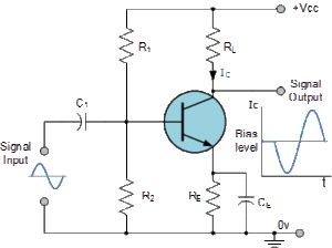
Class-A amplifier, which has a centered Q point. Therefore, the transistors operate only over the linear region of its load line. So, it is an amplifier in which the circuit output current flows throughout the complete cycle of the input signal, i.e., the conduction angle is 360o. In other words, the transistors remain forward-biased right through the input cycle.
Classification of Amplifiers

Amplifiers are classified based on operating principles: Class-A for excellent sound quality but less efficiency, Class-B for higher efficiency but crossover distortion, Class-AB combining both, and Class-D is highly efficient and widely used in portable devices. Each class has pros and cons, with the choice depending on specific requirements like audio quality or power efficiency. Class-A amplifiers provide clean amplification but generate more heat due to constant conduction. Class-D amps are efficient using PWM techniques but may introduce switching noise. Class-AB amplifiers strike a balance with feedback circuits. The selection should consider power needs, audio content, and available resources.
Here are the main classifications of amplifiers:
Based on the Input Signal
- Voltage Amplifiers: Amplify voltage signals and are most commonly used in electronic systems. They take a low-level input voltage and produce a higher-level output voltage.
- Current Amplifiers: As the name suggests, current amplifiers amplify current signals. They take a low-level input current and produce a higher-level output current.
Based on the Number of Inputs and Output
- Single-Input, Single-Output (SISO) Amplifiers: These amplifiers have one input and one output. Common examples include common-emitter transistor amplifiers and operational amplifiers (op-amps).
- Single-Input, Multiple-Output (SIMO) Amplifiers: SIMO amplifiers have a single input but can drive multiple outputs. Class AB and Class D audio amplifiers are examples of SIMO amplifiers.
- Multiple-Input, Single-Output (MISO) Amplifiers: MISO amplifiers have multiple inputs but produce a single output. An example is a summing amplifier that combines various input signals.
- Multiple-Input, Multiple-Output (MIMO) Amplifiers: MIMO amplifiers have multiple inputs and outputs. They are commonly used in advanced communication systems.
Based on Frequency Range
- Audio Amplifiers: Amplifiers are designed to handle audio frequency signals, typically from 20 Hz to 20 kHz. They are used in audio systems, headphones, and speakers.
- Radio Frequency (RF) Amplifiers: These amplifiers are designed to operate at higher frequencies, typically from a few kilohertz to several gigahertz. They are used in wireless communication systems and RF circuits.
Based on Configuration
- Common-Emitter (CE) Amplifiers: A transistor amplifier with the emitter as the common terminal between the input and output.
- Common-Base (CB) Amplifiers: A transistor amplifier with the base as the common terminal between the input and output.
- Common-Collector (CC) Amplifiers: A transistor amplifier with the collector as the common terminal between the input and output.
- Class A, B, AB, C, D, and E Amplifiers are classified based on operating point and conduction angles. Each class has specific advantages and disadvantages.
Based on Amplification Mechanism
- Analog Amplifiers: Amplifiers amplify continuous signals without quantization or discrete levels. They are used in audio and instrumentation applications.
- Digital Amplifiers: Amplifiers that amplify discrete digital signals, often using techniques like pulse-width modulation (PWM). They are commonly used in Class D audio amplifiers.
Based on Application
- Operational Amplifiers (Op-Amps): High-gain, differential amplifiers with versatile applications in signal processing, filtering, and analog computations.
- Power Amplifiers: Amplifiers designed to deliver high-power output signals to drive speakers, motors, or other high-power devices.
- Instrumentation Amplifiers: Specialized amplifiers are used to measure small signals accurately in sensor and measurement applications.
Characteristics of Class-A Amplifier
- While the transistor functions over the linear portion of the load line, the input and output waveforms are the same. For this reason, class-A amplifiers are characterized by high output reliability.
-
Since its operation is constrained only over a small central region of the load line, this class-A amplifier is meant only for amplifying the input signals of small amplitude. Large signs will move the Q-point into non-linear parts near saturation or cut-off. Therefore, it creates distortion.
-
Due to the input signal amplitude restriction, the AC power output for each active device is small.
-
The overall efficiency of the class-A amplifier circuit is
-
The collector efficiency of a transistor is defined as
Class-A Amplifier: Power Distribution

The figure shows the connection of the common-emitter transistor, which forms the active element of a single-stage class-A amplifier. The figure-b shows its output characteristics with a centered Q point.
When an input signal is applied, the “Q point” moves up and down from its central position. The output current also will increase or decrease from its quiescent value ICQ. Similarly, collector-emitter voltage VCE will increase or drop from its quiescent line. The average value of the collector current is ICQ because positive and negative input signal swings will produce equal changes in ICQ.
Transistor Current Components

Collector Current (Ic)
- Collector current (Ic) flows from the collector terminal to the emitter terminal in a bipolar junction transistor (BJT).
- The main current represents the amplified output current in an active mode of operation.
Emitter Current (Ie)
- Emitter current (Ie) is the total current flowing into the emitter terminal of a bipolar junction transistor (BJT).
- It is the sum of the base current (Ib) and the collector current (Ic), as per Kirchhoff’s current law (Ie = Ib + Ic).
Base Current (Ib)
- Base current (Ib) flows into the base terminal of a bipolar junction transistor (BJT).
- It controls the amount of collector current (Ic) flowing through the transistor and amplifies it.
Gate Current (Ig)
- Gate current (Ig) flows into the gate terminal of a field-effect transistor (FET).
- It controls the conductivity of the channel between the source and drain terminals in FETs.
Drain Current (Id)
- Drain current (Id) flows from the drain terminal to the source terminal in a field-effect transistor (FET).
- It represents the amplified output current in an active mode of operation.
Source Current (Is)
- Source current (Is) is the total current flowing out of a field-effect transistor (FET) source terminal.
- It is the sum of the gate current (Ig) and the drain current (Id), as per Kirchhoff’s current law (Is = Ig + Id).
Collector Current vs. Emitter Current (Ic vs. Ie)
- In a well-designed and properly biased BJT, the collector current (Ic) is approximately equal to the emitter current (Ie).
- This relationship holds for most practical applications, and the small difference between Ic and Ie is usually attributed to the base current (Ib).
Drain Current vs. Source Current (Id vs. Is)
- The drain current (Id) equals the source current (Is) in a properly biased FET.
- This relationship is active for most FET circuits, where the gate-source voltage (Vgs) is within the specified operating range.
Transformer Coupled Class-A amplifier.

-
The efficiency of a direct coupled class-A amplifier is poor. This problem can be solved using a proper transformer to connect the load to the amplifier, as shown in the figure below.
-
Since the load is not directly coupled to the collector terminal, the DC collector current does not flow through it. In an ideal transformer, the primary winding resistance is zero. Therefore, DC power loss is zero in the load.
-
In short, the transformer substitutes AC load for ohmic or DC shipment.
Conclusion
In conclusion, Class-A amplifiers excel in applications that prioritize sound quality, linearity, and low distortion over power efficiency. Their remarkable performance in these aspects has earned them a special place in high-fidelity audio and precision signal processing. However, when considering their implementation, careful thermal management and power considerations are necessary to harness the full potential of Class-A amplifiers effectively.
