Fuse

Intriguing Characteristic Parameters and Laws of Fuses

Often seen as simple components, fuses possess an intricate interplay of characteristic parameters and are subject to fascinating laws that govern their behavior. These unassuming devices play a crucial role in safeguarding electrical systems from overcurrents, and delving into their intriguing world sheds light on their true complexity. A fuse can conduct continuously at maximum current without interrupting the circuit.

Characteristics and Parameters of Fuse

Fuses are essential components in electrical systems, providing vital protection against overcurrents and ensuring our devices’ and infrastructure’s safety and reliability. Understanding the characteristic parameters of fuses is crucial for selecting the right fuse for a specific application.

Speed

slow-blow-vs-fast-blow-fuse

The fuse’s blown speed depends upon the current flows through the circuit and the type of material used to make the fuse. The operating time of the fuse is not a fixed interval, whereas it decreases when the current increases. The fuses’ working time has different characteristics compared to the present, characterized as fast-blow or time-delay, according to the time response to an over-current condition. Normally fuse requires double the time of its rated current to blow in .1 sec, and a slot blow fuse requires to double its rated current for 10 sec to blow.

The selection of fuse may depend on the characteristics of the load. Fast or ultra-fast fuses are used in semiconductor devices because they heat rapidly when an over-current flows. Most responsive electrical equipment requires the fastest blowing fuses since exposure to an overload current could highly damage the electrical machines. These kinds of fuses are used for general purposes. The slow blow fuse (time-delay fuse) is designed to permit the current through the fuse above the rated value for a short interval without blowing a fuse. These fuses are used in motors, which can draw larger rated currents for quite a few seconds while coming up to their rated speed.

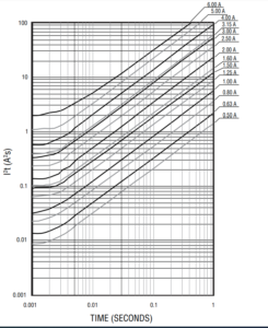
I2T Value

I2T Value

The quantum of energy depleted by the fuse element to clear the electrical faults. This expression is normally used in short circuit conditions, and the values are used to perform coordination studies in an electrical network. I2T parameters are provided by the chart in manufacturer data sheets for every fuse. The fuse coordination operations with upstream or downstream devices, melting I2T and clearing I2T, are specified. The melting I2T equals the energy required to begin melting the fuse element. The clearing I2T is proportional to the overall energy permit by the fuse once a fault is cleared. The energy primarily relies on current and time for fuses and the available fault level and system voltage. Since the I2T rating of the fuse is proportional to the energy it allows, it measures the thermal damage and magnetic forces that a fault will produce.

Breaking Capacity

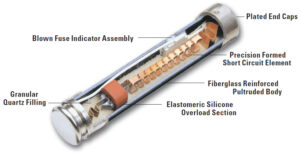
hrc-fuse-construction

The breaking capacity is the maximum current that can safely be interrupted by the fuse. Generally, this should be higher than the prospective short circuit current. Miniature fuses may have an interrupting rating of only ten times their rated current. Some fuses are designated HRC (High Rupture Capacity) and are regularly packed with sand or related material. Fuses for small, low-voltage, residential wiring systems are normally rated to interrupt 10,000 amperes. Likewise, larger power system fuses have higher interrupt ratings, with some low voltage current limiting interrupting fuses rated for 30,000 amperes. The total apparent power of the fault level on the circuit rates fuses for high-voltage equipment up to 1,15,000 volts.

Rated Voltage

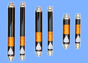
high-voltage-hrc-fuse

The fuse voltage rating must be greater than or equal to what would become an open circuit voltage. For instance, a glass tube fuse rated at 32V would not interrupt current from a voltage source of 120V or 230V. If a 32-volt fuse attempts to interrupt the 120V or 230V supply, an arc may appear. Plasma inside the glass tube fuse may keep on conducting current until the current ultimately diminishes that plasma reverts to an insulating gas. The rated voltage should be larger than the maximum voltage source it would have to disconnect. The rated voltage remains the same for any fuse when related fuses are connected in series. Connecting fuses in sequence does not increase the rated voltage of the combination.

Voltage Drop

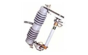
high voltage drop out fuse

A voltage drop across the fuse is frequently provided by its manufacturer. Resistance of the fuse element may vary when it becomes hot due to energy dissipation while conducting higher currents. This resulting voltage drop should be considered, predominantly when using a fuse in low-voltage applications. Voltage drop frequently is not important in traditional wire-type fuses but can be significant in other technologies, such as resettable (PPTC) type fuses.

Voltage derating

smps-switch-on-curve

Ambient temperature will change fuses operational parameters. A fuse rated 1Amps at 25oC may conduct up to 10% or 20% more current at 40oC and may open at 80% of its rated at 100oC. Operating values will vary with each fuse family and are provided in manufacturer data sheets.

Fuse Materials

fuse-material

Fuses are manufactured in different sizes and styles to provide in many applications, manufactured in standardized package layouts to make them easily interchangeable. Depending on application and voltage class, the fuse bodies may be made of ceramic, glass, Plastic, fiberglass, Molded mica laminates, or molded compressed fiber.

Laws of Fuse

It determines the current carrying capacity of a fuse wire. The fuse carries the usual current at stable conditions without raising its normal temperature to the melting limit. In this condition, heat generated from the wind through the fuse wire equals heat dissipated.
Heat generated     = I2R
                             = I2ρ (l/a)
                             = 4I2Ρl / πd2
Since a= πd2/4
Where
           R – is the resistance of the fuse wire.
           ρ – is the resistivity,
           l  – is the length and
           a  – is the cross-sectional area of the fuse wire.
                             = I2K1(l/d2)  ——–>1
Where K1 is a constant. Heat lost ∝ surface area of fuse wire ∝ πdl.
∴ Heat Loss = k2dl  ———–>2
Equating 1 & 2, we get
                             I2K1(l/d2) = k2dl
                             I2 = Kd3
Where K =K2/K1
                              I = Kd3/2
                              I = Kd1.5
This is known as fuse law.

Laws of the Magnetic Circuit

Magnetic Circuit

It stated that the laws governing the steady flow of electricity in a circuit may readily be modified. To be at once applicable to the magnetic circuit. Thus

Magnetomotive Motive Force = Flux x Reluctance

F= Φ x S

Corresponding exactly to Electromotive Force = Current x Resistance

Reluctance = (length/area) x (1/Permeability)

= l/Aμ

For a magnetic of a uniform sectional area corresponding exactly to

Resistance = (length/area) x (1/conductivity)

It is often convenient to calculate in terms of unit dimensions. We then have

m.m.f per unit length = Flux x Reluctance per unit length

= (Flux/area) x (l/permeability)

= Flux density x (l/permeability)

Magnetic Field Intensity H = B/μ

This corresponds exactly to,

For a material carrying a uniform distributed flux and of length l, then the total m.m.f is then equal to the m.m.f per unit length x l

i.e. F=Hl or AT=Hl

For dealing with a magnetic circuit in which the flux has to permeate some different portions in seconds, the methods employed for coping with series electric circuits can at once be applied, the total reluctance being the sum of the values for the various portions. Normally, the importance of the reluctance is only of the moment in so far as it permits a deal being determined for the m.m.f required to establish a given flux in the circuit. It is often the simplest method to determine this value of the total m.m.f by summing the values of m.m.f necessary to establish the change through the various parts of the circuit. This aligns with calculating the total voltage drop in an electric circuit by summing the voltage drop values in the multiple components.

Thus the total value of the m.m.f facing around a complete magnetic is given by

AT (or) F = ∫Hdl

Or where the circuit consists of some homogeneous parts, each of uniform cross-section and length l1, l2, etc.

Total m.m.f        F (or) AT = Σ Hl = H111 + H2l2 + ….

= Φ [S1 + S2 + ….]

If the values for the area and permeability of the various portions of the circuits are, respectively, A1, μ1, etc., the total m.m.f becomes

AT (or) F = (B11)l1 + (B22)l2 + …..

Where B1 = Φ/A1 etc

Occasionally it is convenient to express the fundamental law of the magnetic circuit in the form.

Flux = magnetomotive force x Permeance

Permeance is nothing but the reciprocal of the reluctance to deal with paths in parallel, and the total Permeance is the sum of the values for the individual courses.

The main difference between electric and magnetic calculations arises from the fact that the resistance of an electric circuit is not directly dependent upon the values of the reluctance of a magnetic substance but is dependent to an enormous extent upon the value of the flux permeating it.

Jessica

Jessica, at just 27 years old, is a passionate trailblazer in the world of physics and engineering. Her insatiable curiosity about the mysteries of the universe and a knack for simplifying complex concepts have made her a rising star in the field. As a Quantum Mechanics Enthusiast, Jessica delves into the deepest realms of theoretical physics with a unique and engaging perspective. Her love for unraveling the secrets of the quantum world is infectious, making even the most perplexing ideas accessible to enthusiasts and newcomers alike.

Leave a Reply

Your email address will not be published. Required fields are marked *