

Exploring the Characteristics of a DC Shunt Generator
Current Division in DC Shunt Wound Generator

In a DC shunt wound generator, the armature current (Ia) divides into two distinct paths, each serving a specific purpose within the generator’s operation. This division of current plays a crucial role in the generator’s functionality and efficiency.
Shunt Field Current (Ish)
A fraction of the armature current, known as the shunt field current (Ish), flows through the shunt field coil or winding. The shunt field coil is connected in parallel to the armature winding and is responsible for creating the magnetic field within the generator’s stator.
- Magnetic Field Generation: The shunt field current generates a constant magnetic field in the stator, which provides the necessary magnetic flux for the generator’s operation.
- Regulation of Terminal Voltage: The generator’s terminal voltage can be regulated by controlling the shunt field current. Adjusting the shunt field current allows the generator to maintain a relatively constant output voltage even under varying load conditions.
Load Current (IL)
The main portion of the armature current, referred to as the load current (IL), flows through the external load connected to the generator’s output terminals. This load current powers various electrical devices or systems connected to the generator.
- Power Generation: The load current is the actual output of the generator, delivering electrical power to connected devices such as lights, motors, appliances, or other electrical loads.
- Voltage Regulation: The division of armature current into shunt field and load current helps maintain a consistent output voltage even when the load varies. The shunt field current controls the generator’s internal magnetic field strength, enabling it to adjust its output voltage as needed.
Open Circuit Characteristic
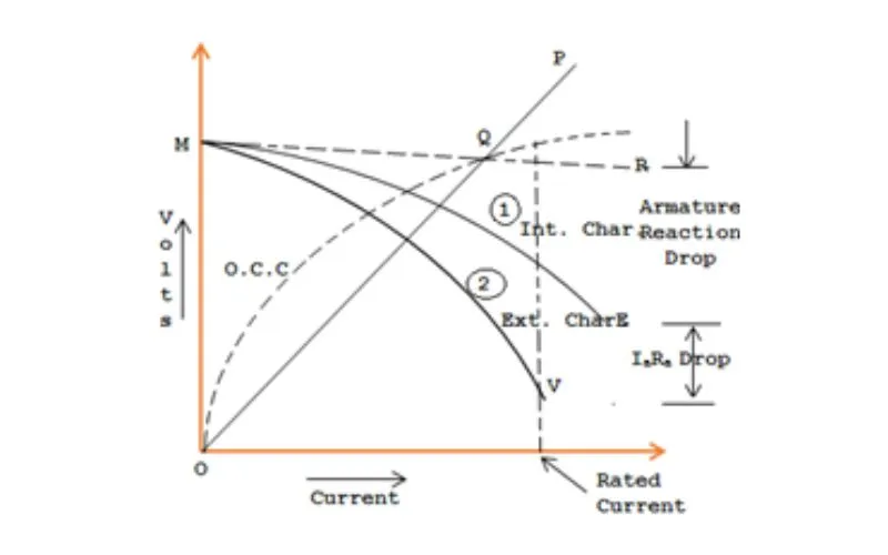
The Fig shows the open circuit characteristic of a DC shunt generator, which is similar in form to that of a series generator. The line OP signifies the shunt field circuit resistance. Once the generator is run at typical speed, it’ll build up a voltage OM. At no load, the generator’s terminal voltage will be constant (= OM) diagrammatical by the horizontal line MR.
Internal Characteristic
External Characteristic
= E-(IL+Ish) Ra
Hence, the external characteristic curve can lie under the internal characteristic curve by an equal amount up to the drop in the armature circuit [i.e., (IL + Ish) Ra].
Efficiency and Performance
Efficiency and performance are paramount when assessing the characteristics of a DC shunt generator. We examine the factors that influence its efficiency, such as armature resistance, losses, and magnetic saturation. Discover the appealing trade-offs between power output, losses, and the generator’s overall efficiency, shedding light on how engineers enhance these characteristics for different applications.
Efficiency Factors
Several factors influence the efficiency of a DC shunt generator:
- Armature Resistance (Ra): Higher armature resistance increases losses and decreases efficiency.
- Field Resistance (Rf): Proper field resistance adjustment influences the terminal voltage regulation and efficiency.
- Losses: Copper losses (Ia²Ra), iron losses (hysteresis and eddy current losses), and mechanical losses (friction and windage) affect the overall efficiency.
- Magnetic Saturation: The saturation of magnetic materials impacts the generator’s ability to generate higher voltages under load.
Optimizing Efficiency and Performance
Engineers strive to balance power output, losses, and overall efficiency. This often involves fine-tuning factors like field resistance, armature resistance, and load distribution to ensure the generator operates efficiently across various loads.
Power Output and Losses
The power output of a DC shunt generator is determined by the product of the load current (IL) and the terminal voltage (V). However, losses within the generator impact the actual power available for external use.
These losses include:
- Copper Losses (Ia²Ra): These losses occur due to the resistance of the armature winding and the current flowing through it. Higher current or resistance leads to increased copper losses.
- Iron Losses: Hysteresis and eddy current losses in the core material contribute to iron losses. These losses increase with the frequency of magnetic reversals in the core.
Mechanical Efficiency
The mechanical efficiency of the generator accounts for losses in the mechanical components of the generator, such as friction and windage losses. These losses reduce the mechanical power available to drive the generator’s rotation.
Optimal Load Distribution
Engineers aim to determine the load at which the generator operates most efficiently. This involves balancing the power output and losses to achieve the highest overall efficiency.
Efficiency Calculation
The overall efficiency of a DC shunt generator is calculated as the ratio of electrical output power to mechanical input power. It is given by the formula: Efficiency (%) = (Output Power / Input Power) * 100
Magnetic Saturation Effects
As the magnetic flux increases, the generator’s core may reach a point of saturation where further increases in excitation current do not result in proportional increases in magnetic flux. This phenomenon can affect the generator’s ability to maintain stable voltage regulation at high loads.
Application-Specific Considerations
The intended application influences the design and operation of a DC shunt generator. For example, careful attention is given to field resistance adjustments in applications where constant voltage is crucial.
Advancements and Modernization
Advancements in materials, control systems, and design techniques have allowed engineers to enhance the efficiency and performance of DC shunt generators. Digital control systems enable real-time adjustments to optimize performance under various conditions.
Conclusion
In conclusion, the characteristics of a DC shunt generator offer a captivating glimpse into the intricate workings of this remarkable device. From its automated nature and magnetic mastery to its excitation control and power output efficiency, the DC shunt generator showcases a host of captivating traits. By understanding these characteristics, engineers can harness the full potential of this device, enabling reliable and efficient power generation for a wide range of applications. As we delve into the fascinating world of electrical engineering, the DC shunt generator remains a timeless testament to the marvels of electricity generation and control.
