

Full Wave Rectifier Diagram: Circuit, Working & Explanation
When you explore full-wave rectifiers, you’ll discover how they efficiently convert AC to DC, providing a steady output with minimal ripple. The diagram typically depicts either a center-tapped transformer with two diodes or a bridge rectifier with four diodes. Understanding this setup is essential, as it influences the rectifier’s performance and application. Curious about how these components work together to achieve seamless conversion? Let’s delve into the details and deepen your understanding of this crucial electrical component.
Key Takeaways
- A full-wave rectifier uses either a center-tapped transformer with two diodes or a bridge configuration with four diodes.
- The output waveform is smoother, with a ripple frequency twice that of the input AC frequency.
- The center-tapped configuration requires diodes that handle the full transformer peak voltage.
- The bridge rectifier configuration does not need a center-tapped transformer.
- Full-wave rectifiers convert both halves of the AC waveform into DC.
Understanding Full Wave Rectifiers
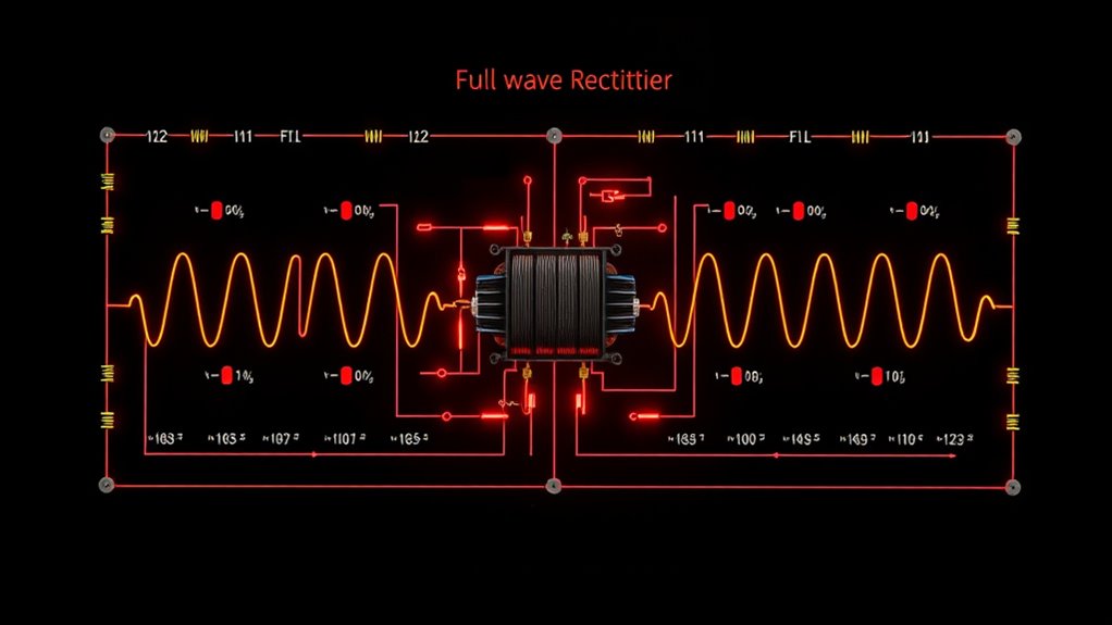
When you delve into the world of full-wave rectifiers, understanding their function is crucial to grasping their importance in electrical circuits.
A full-wave rectifier efficiently converts AC to DC by transforming both halves of an AC waveform into pulsating DC. You can achieve this with a center-tapped transformer and two diodes or, more commonly, a bridge configuration using four diodes.
This setup increases the average DC output voltage to about 0.637 times the peak voltage, offering a more consistent DC output. The ripple frequency is twice the AC input frequency, resulting in a smoother output, especially when smoothing capacitors are used.
The efficiency of a full-wave rectifier can reach nearly 100%, thereby minimizing energy waste and optimizing the AC-to-DC conversion process.
Circuit Design of Full-Wave Rectifiers
Although designing a full-wave rectifier circuit may seem intimidating, understanding the core components makes it a straightforward process. You can choose between a center-tapped transformer setup or a bridge configuration.
The center-tapped transformer uses two diodes, each conducting during its respective AC cycle, providing a continuous DC output across the load resistor. Alternatively, the bridge configuration employs four diodes, eliminating the need for a center tap and ensuring unidirectional current flow throughout the AC cycle.
The output waveform in both setups has a frequency that is double that of the input, resulting in a smoother, higher average DC output of approximately 0.637 Vmax.
Selecting diodes with the correct peak inverse voltage rating and an appropriate load resistor is essential for achieving peak performance in your full-wave rectifier circuit.
Comparing Center-Tapped and Bridge Configurations
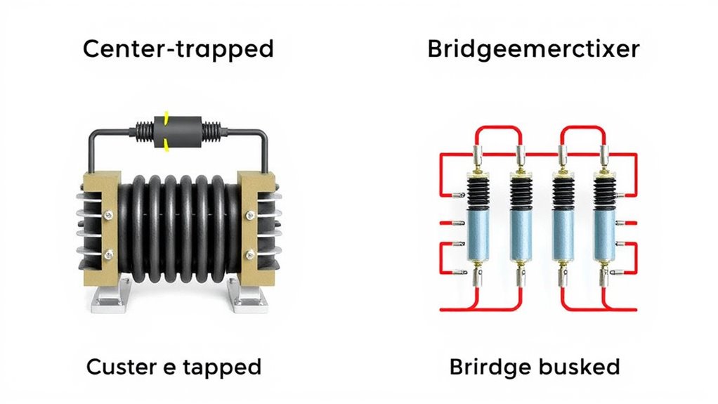
Although both center-tapped and bridge rectifiers serve the same purpose of converting AC to DC, each has distinct advantages and trade-offs worth considering.
A center-tapped full-wave rectifier uses a transformer with a center tap and requires two diodes to rectify both halves of the AC cycle. In contrast, a bridge rectifier uses four diodes, eliminating the need for a center-tapped transformer.
Both configurations offer similar efficiency and output voltage around 0.637Vmax, but the bridge rectifier is more compact and cost-effective.
A significant difference lies in the Peak Inverse Voltage (PIV) requirements; center-tapped diodes must handle the full transformer peak voltage, whereas bridge rectifiers handle only half.
Additionally, bridge rectifiers often produce lower ripple voltage, thereby enhancing the smoothness of the output.
Analyzing Output Waveforms
When analyzing the output waveforms of a full-wave rectifier, it’s essential to focus on smoothing techniques that enhance DC quality by minimizing ripple voltage.
You’ll notice that each diode conducts during different halves of the AC cycle, doubling the effective frequency and reducing fluctuations.
Waveform Smoothing Techniques
Smoothing capacitors play a crucial role in full-wave rectifier circuits by reducing AC ripple and enhancing the average DC output.
In a full-wave rectifier, the pulsating DC output has a ripple frequency that’s double the input AC frequency, making filtering more efficient. By using a smoothing capacitor, you can minimize ripple voltage, improving the quality of your output.
The capacitance value is vital; increasing it—from 5 μF to 50 μF, for example—can significantly reduce ripple voltage and enhance stability.
Additionally, incorporating a π-filter configuration further diminishes ripple voltage, ensuring a consistent DC output. This is especially important when dealing with sensitive electronic devices.
Ripple Voltage Analysis
Ripple voltage is a crucial aspect to contemplate when analyzing output waveforms in full-wave rectifiers. In this setup, ripple voltage frequency is double the AC input, effectively smoothing the DC output.
You can calculate it using the formula ( V_{text{ripple}} = frac{I_L}{2 cdot f cdot C} ), where ( I_L ) is load current, ( f ) is frequency, and ( C ) is the smoothing capacitor’s capacitance.
Increasing the capacitor’s value reduces ripple voltage, enhancing energy storage and output stability. With a ripple factor of approximately 0.48, full-wave rectifiers outperform half-wave versions.
For even better performance, consider a π-filter. This addition significantly reduces ripple voltage, making the DC output more stable and suitable for use with sensitive electronics.
Diode Conducting Cycles
In a full-wave rectifier, the diode’s conducting cycles play a crucial role in shaping the output waveform.
During the positive half of the AC input waveform, diode D1 conducts, allowing current to flow through the load resistor in one direction, while diode D2 remains reverse-biased. Conversely, during the negative half, D2 conducts, maintaining the same current direction, and D1 is reverse-biased.
This results in a pulsating DC output with a ripple frequency that’s twice the input frequency, creating a smoother waveform. The average DC output voltage is 0.637 times the peak voltage, higher than in half-wave rectifier circuits.
These cycles guarantee efficient current flows, enhancing the performance of rectifier circuits and providing a consistent power supply to connected devices.
Role of Smoothing Capacitors
When it comes to full-wave rectifier circuits, you’ll find that smoothing capacitors play an essential role in guaranteeing a stable DC output. They store and discharge energy to reduce ripple voltage, enhancing the average DC output. The ripple frequency is twice the supply frequency, so smoothing capacitors charge and discharge more frequently, maintaining voltage stability. The load resistance affects how quickly the capacitor discharges; lower resistance requires a larger capacitor for a table output. Including a π-filter with inductors and capacitors further decreases ripple.
| Component | Role |
|---|---|
| Smoothing Capacitor | Reduces ripple voltage |
| Load Resistance | Influences the capacitor discharge |
| Ripple Frequency | Double supply frequency |
| π-filter | Enhances voltage stability |
| Capacitor Size | Affects the average DC output |
Selecting the correct capacitor size ensures optimal performance.
Calculating Key Parameters
As you explore calculating key parameters for a full wave rectifier, understanding the formulas is vital for optimizing performance.
Begin with the average (DC) output voltage, calculated as V_dc ≈ 0.637 × V_max, where V_max is the peak voltage of the input AC voltage.
Next, determine the ripple voltage using V_ripple = I_L / (2 × f × C), taking into account the load current and the smoothing capacitor.
The peak inverse voltage (PIV) is essential for diode selection, equaling the transformer’s maximum voltage.
Rectification efficiency stands at about 81.2%, showcasing effective power conversion.
Finally, the transformer utilization factor (TUF) is 0.693, highlighting efficient transformer usage.
These calculations ensure your full-wave rectifier operates efficiently and reliably.
Advantages of Full Wave Rectifiers
Although full-wave rectifiers might seem complex at first glance, they offer numerous advantages that make them indispensable in electronic circuits. By utilizing both halves of the AC cycle, a full-wave rectifier nearly doubles the average output voltage compared to its half-wave counterpart. This results in a smoother DC output, which greatly reduces ripple and voltage fluctuations.
The rectification efficiency of approximately 81.2% surpasses that of half-wave rectifiers, providing a stable DC output ideal for various applications. Using a bridge rectifier configuration with fewer components, you can convert AC to DC without needing a center-tapped transformer, lowering costs and complexity.
- Higher average output voltage
- Stable and smoother DC output
- Increased rectification efficiency
- Reduced ripple frequency
- Fewer components with a bridge rectifier
Challenges and Solutions in Implementation

Implementing a full-wave rectifier presents unique challenges, primarily due to the complexity of using four diodes in a bridge configuration.
You’ll need to ensure these diodes have a high Peak Inverse Voltage (PIV) rating to handle the maximum reverse voltage and prevent failures. Managing heat dissipation is essential, as the diodes generate significant heat; using heatsinks can effectively control the temperature.
To mitigate ripple voltage, larger smoothing capacitors are essential, as they stabilize the DC output and improve efficiency.
Additionally, using a transformer with the correct turns ratio is crucial for achieving the desired output voltage and current. This setup not only optimizes efficiency but also ensures that the full-wave rectifier operates reliably, delivering a steady output voltage with minimal fluctuations.
Conclusion
In wrapping up your exploration of full-wave rectifiers, you’ve investigated their circuit designs, comparing center-tapped and bridge configurations. You’ve analyzed output waveforms and understood the essential role of smoothing capacitors in minimizing ripple. By calculating key parameters, you’ve seen the advantages these rectifiers offer, like an efficient DC supply. You’re now better equipped to tackle challenges in implementation, ensuring ideal performance for your electronic projects. Keep experimenting and refining your understanding!
FAQs
1. What Is a Full Wave Rectifier With Diagram?
You want to understand a full wave rectifier, which converts AC to DC using diodes. It doubles the output frequency for smoother DC. Refer to diagrams to determine whether the configuration is center-tapped or bridge, illustrating diode arrangements and output measurement.
2. What Is the Difference Between a Bridge Rectifier and a Full Wave Rectifier?
You’re comparing a bridge rectifier and a center-tapped full-wave rectifier. The bridge utilizes four diodes without a center tap, providing a higher output voltage and lower PIV requirements, while being more compact and cost-effective.
3. What Are the Advantages of a Full Wave Rectifier?
You’ll find full-wave rectifiers advantageous because they efficiently utilize both halves of the AC waveform, providing a higher average DC output, reduced ripple, and improved stability, making them ideal for applications that require a consistent power supply without a center-tapped transformer.
4. Is a Full Wave Rectifier AC or DC?
A full-wave rectifier transforms AC into DC. You’re using it to convert alternating current into a smoother direct current. It leverages both halves of the AC waveform, ensuring a more stable and efficient DC output.
