

TRIAC Circuit: A Complete Beginner-Friendly Guide
A TRIAC circuit is a smart electronic switch that works with AC (alternating current) power. It is found in devices like dimmer switches, fan regulators, and even smart home systems. TRIACs are popular because they control electrical power smoothly and silently without any moving parts. In this article, you’ll learn what a TRIAC is, how it works, and where it’s used. Whether you’re a student, hobbyist, or electronics enthusiast, understanding TRIACs is essential for working with AC-powered circuits. They offer a compact, low-maintenance alternative to mechanical switches and relays. By mastering TRIAC circuits, you’ll gain greater control over automation, energy efficiency, and device performance.
What Is a TRIAC?

TRIAC stands for Triode for Alternating Current. It is a semiconductor device that controls AC power by allowing current to flow in both directions. Unlike a simple switch that can only turn power on or off, a TRIAC can also control the amount of power reaching a device. This makes it helpful in dimming, speed control, and temperature regulation.
TRIACs are part of a larger group of components called thermistors. However, unlike other thermistors, such as the SCR (Silicon Controlled Rectifier), the TRIAC conducts electricity during both halves of the AC cycle — the positive and negative halves of the cycle. This feature makes it very useful in many household and industrial appliances that use alternating current (AC) electricity.
Parts of a TRIAC
A TRIAC has three terminals:
- MT1 (Main Terminal 1): One end of the main current path.
- MT2 (Main Terminal 2): The other end of the main current path.
- Gate (G): The control terminal that receives a small signal to switch the TRIAC on.
The gate works like a trigger. When a small voltage is applied to the gate, it turns the TRIAC on, allowing a much larger current to pass between MT1 and MT2. The TRIAC stays on until the current naturally stops flowing, which happens at the end of each AC half-cycle.
This behavior makes TRIACs self-commutating, meaning they don’t require an additional signal to turn off. They switch off automatically when the current goes to zero.
How Does a TRIAC Work?
To understand how a TRIAC works, imagine it as a controlled doorway for electric current. The door stays closed until someone knocks (the gate signal). Once it’s open, electricity flows until the current naturally stops, usually at the end of an AC half-cycle.
Operation in Detail:
- AC Voltage Applied: Voltage is applied between MT1 and MT2. No current flows yet because the TRIAC is off. At this stage, the TRIAC behaves like an open switch. The connected load (like a bulb or motor) remains inactive until the TRIAC is triggered.
- Triggering: A small signal is applied to the gate. This turns the TRIAC on. The gate signal is often a short pulse that is timed carefully during each AC half-cycle. Once the gate receives the pulse, the TRIAC instantly switches to its conducting state.
- Conduction: The TRIAC allows current to pass in both directions (forward and reverse), depending on the AC waveform. This conduction continues for the rest of that AC half-cycle. The amount of power delivered to the load depends on when the TRIAC is turned on during the cycle.
- Switch-Off: When the AC cycle crosses zero (zero-crossing point), the current drops, and the TRIAC turns off. This is known as natural commutation, as no additional signal is required to switch it off. The TRIAC remains off until it receives another gate pulse in the next half-cycle.
- Cycle Repeats: Another gate signal is needed to turn it on in the next half-cycle. This allows the TRIAC to control each half of the AC wave individually. By adjusting the gate timing, you can control the amount of power delivered to the load in each cycle.
This process repeats many times each second (approximately 50 or 60 times per second per cycle), allowing for fine control over how much of the AC signal reaches the connected device.
Basic TRIAC Circuit
A basic TRIAC circuit usually includes:
- A TRIAC (e.g., BT136)
- A gate resistor
- A DIAC (optional for improved triggering)
- A load (such as a lamp or fan)
- A capacitor (if phase control is needed)
The TRIAC is placed in series with the load (such as a lamp), and a triggering network is connected to its gate. The gate receives a timed signal — either from a direct voltage source or through a DIAC-capacitor network — that turns the TRIAC on during each half-cycle of the AC.
The timing of the gate signal is crucial. Triggering it early in the AC cycle delivers more power to the load. Triggering it later reduces power. This is how dimmers and speed controllers adjust the amount of electricity flowing to devices.
TRIAC in Dimmer Circuit
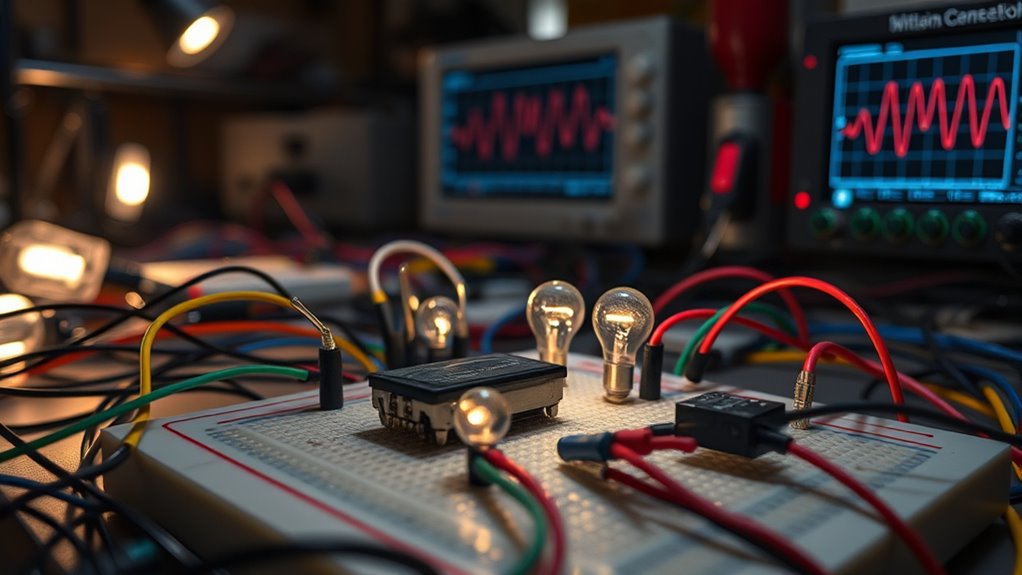
TRIAC circuits are most famous for their role in light dimmers. A light dimmer allows you to adjust the brightness of a bulb by controlling the amount of the AC wave that reaches it.
Here’s how it works:
- A variable resistor (potentiometer) and a capacitor create a delay. The capacitor charges at a rate set by the resistor.
- When the voltage across the capacitor reaches a certain threshold, it triggers a DIAC, which in turn sends a signal to the TRIAC.
- The TRIAC turns on and conducts electricity for the rest of the AC half-cycle.
- The longer the delay, the dimmer the light, because the TRIAC is on for a shorter portion of the AC wave.
This phase control allows smooth adjustment without any flicker or noise. The same method is used in fan speed regulators, heater controls, and basic AC motor speed controllers.
Applications of TRIAC Circuits
TRIACs are used in a wide range of AC power control systems. They are efficient, long-lasting, and cost-effective.
| Application | Description |
| Light Dimmers | Adjust brightness by controlling the AC wave timing |
| Fan Speed Controls | Adjust the fan’s speed based on the power delivered |
| Heater Controls | Regulate the temperature in electric heaters by controlling power |
| AC Motor Drives | Turn motors on/off or vary their speed in tools and appliances |
| Washing Machines | Control the drum motor speed and water heating system |
| Electronic Switches | Replace mechanical relays in automation systems |
| Smart Home Devices | Used in home automation for lighting and appliance control |
These circuits are also common in energy-saving devices, where the goal is to reduce electricity usage by adjusting the amount of power delivered to a device.
Advantages of Using TRIACs
TRIACs offer many benefits over traditional switches or relays:
- Two-Way Control: Can handle both directions of AC, which is perfect for AC power control.
- Silent Operation: Unlike mechanical relays, TRIACs operate silently.
- No Moving Parts: This means longer life, lower maintenance, and fewer failures.
- Low Trigger Power: The gate requires minimal energy to activate the device.
- Compact Design: Saves space in electronics and appliances.
- Fast Switching: Can respond quickly to control signals, making them suitable for precise applications.
Due to these features, TRIACs are a popular choice in low- to medium-power applications across various industries.
Limitations of TRIAC Circuits
While TRIACs are versatile and widely used for AC power control, they are not ideal for every situation. It’s important to understand their limitations before choosing them for a specific application. Here are some common challenges associated with TRIAC circuits:
Sensitive to Electrical Noise
TRIACs can be unintentionally triggered by electrical noise, voltage spikes, or power surges on the AC line. This can cause the TRIAC to turn on unexpectedly, leading to unwanted operation of the connected device.
Solution: Utilize snubber circuits, filters, or optoisolators to suppress noise and enhance stability.
Less Suitable for Inductive Loads
When controlling inductive loads such as motors, solenoids, or transformers, TRIACs may experience voltage spikes or erratic behavior due to the energy stored in the magnetic field. This can lead to false triggering or even damage the TRIAC over time.
Solution: Add protective components, such as MOVs (Metal Oxide Varistors) or RC snubber networks, to absorb voltage transients.
Limited Power Handling Capacity
TRIACs are typically designed for low to medium-power applications. When used in high-power environments (e.g., industrial heating systems or large motors), they may overheat or fail if the current exceeds their rated capacity.
Solution: For high-power applications, consider using thyristors, GTOs, or IGBTs that are better suited for handling heavy electrical loads.
Electromagnetic Interference (EMI)
TRIACs use phase control to modulate the power delivered to a load, which involves switching on and off rapidly within each AC cycle. This sudden switching action can generate electromagnetic interference (EMI), which may affect nearby sensitive electronic devices or communication systems.
Solution: Implement EMI filters and follow shielding and grounding best practices to minimize interference.
Despite these limitations, careful design and proper filtering can reduce most issues.
TRIAC vs SCR
Although both TRIACs and SCRs are used in power electronics, they have different characteristics.
| Feature | TRIAC | SCR |
| Conducting Mode | Both directions (AC) | One direction (usually DC or half AC) |
| Terminals | MT1, MT2, Gate | Anode, Cathode, Gate |
| Common Use | AC load control (dimmers, fans) | DC rectifiers, power converters |
| Triggering | Positive or negative gate pulses | Usually, a positive pulse only |
| Switching Off | At the zero crossing of AC | Requires a circuit breaker or commutation |
If you need control over both halves of the AC wave, a TRIAC is the better choice.
Example Use Case: AC Fan Speed Controller
An AC fan controller using a TRIAC allows you to easily set the speed of a ceiling or exhaust fan. The TRIAC is triggered later in the AC cycle for slower fan speed and earlier for faster speed. The variable resistor allows you to adjust this delay, thereby controlling the fan’s power smoothly and efficiently.
This technique is safer and more energy-efficient than using mechanical speed selectors. It’s also very quiet, making it great for bedrooms, offices, or libraries.
Final Words
The TRIAC circuit is a type of Triode for alternating current used to control AC power in many electronic applications. It is used for precise, silent, and reliable switching over mechanical relays. Unlike relays that make loud clicks and are easily mechanically damaged, TRIACs work quietly and have no moving parts. These circuits are found in light dimmers for brightness adjustment and in-ceiling or exhaust fans for speed regulation, respectively. Understanding how and where TRIACs work will improve the design and functionality of your electronic projects. It also helps diagnose and repair household electronics more effectively, making TRIACs an indispensable component of modern electrical and electronic systems.
FAQs
1. What is a TRIAC used for?
A TRIAC is commonly used for controlling AC power in applications such as light dimmers, fan speed regulators, heater controls, and motor speed controllers. It allows smooth and silent adjustment of electrical power to connected devices.
2. How does a TRIAC differ from an SCR?
While both are semiconductor switches: A
- TRIAC can conduct current in both directions and is primarily used in AC circuits.
- SCR (Silicon Controlled Rectifier) only conducts in one direction and is more suited for DC or unidirectional AC applications.
3. How many terminals does a TRIAC have?
A TRIAC has three terminals:
- MT1 (Main Terminal 1)
- MT2 (Main Terminal 2)
- Gate (G) — used to trigger the TRIAC into conduction.
4. Can TRIACs control both the voltage and current?
TRIACs primarily control the timing of current conduction, effectively regulating power to the load. They don’t directly adjust voltage or current levels, but they influence the amount of power delivered by delaying conduction during each AC cycle.
5. Why is a DIAC used with a TRIAC?
A DIAC is often used to provide a sharper, more reliable triggering pulse to the TRIAC. It helps improve the stability of switching and is commonly found in phase-control circuits, such as dimmers for lighting.