

Under Frequency | Negative Sequence Relay
The Under Frequency | Negative Sequence Relay is critical in modern power systems that ensure stability and protection. As electricity demand fluctuates and unforeseen events occur, such as faults or disturbances, the frequency and voltage levels in the grid can deviate from their normal values. This relay, also known as the UF/NS relay, is designed to monitor and detect under-frequency and negative sequence conditions, which could lead to potentially harmful consequences if not addressed promptly. In this context, the relay acts as a vigilant guardian, swiftly triggering protective actions to prevent further damage and maintain the integrity of the power system. Understanding the principles and functionalities of the Under Frequency | Negative Sequence Relay is essential for power engineers and operators, as it forms a critical defense line against system instability and potential outages.
Under Frequency Relay
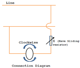
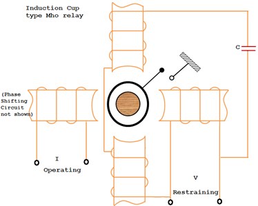
Protective relay
Directional Over Current Relay
The Directional Over Current Relay, commonly known as the DOCR, is a fundamental protective device in electrical power systems to detect and respond to faults and abnormal conditions. Unlike conventional overcurrent relays based solely on the magnitude, the DOCR is equipped with directional elements, allowing it to selectively operate in specific directions along the power network. This directional feature enables the relay to discriminate between faults occurring in its protected zone and those originating from external sources, preventing unnecessary tripping and isolating only the affected part of the system. By swiftly detecting defects and coordinating with other protective devices, the Directional Over Current Relay plays a pivotal role in safeguarding the integrity and stability of the power grid, minimizing outage durations, and enhancing the overall reliability of electrical networks. Power system engineers heavily rely on the DOCR’s accurate and fast response to maintain the safety and efficiency of electricity transmission and distribution, making it an indispensable component in modern electrical infrastructure.
Negative Sequence Relay
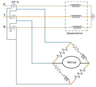
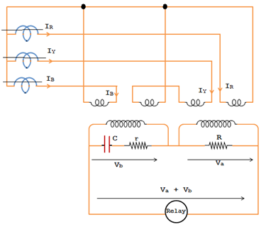
The arrangement of the negative sequence relay connection is shown in the figure. The relay is connected in parallel across the current transformer secondaries. Under normal conditions, their algebraic sum is zero as equal current flows in all three phases. Hence no current flows through the relay. But, if unbalancing occurs, the secondary currents will be different, and the resultant current flows through the relay, and the relay operation trips the circuit breaker to disconnect the generator from the system.
Types of Electromagnetic Relays
Electromagnetic relays, widely used in various applications for their simplicity and reliability, come in different types to suit specific requirements. The most common types of electromagnetic relays include the following:
Attracted Armature Relay
This classic type features a pivoted armature attracted to an electromagnet when a current passes through the coil, causing the contacts to switch positions. Drew armature relays are used in low-power applications and control circuits.
Induction Disc Relay
Operating on the principle of electromagnetic induction, this relay employs a rotating disc driven by the interaction of magnetic fields. The disc’s movement actuates the contacts, making it suitable for high-current applications and offering inherent time delay features.
Polarized Relay
Using a permanent magnet in addition to an electromagnet, polarized relays provide greater sensitivity and improved directional characteristics for specific applications like protective relaying.
Differential Relay
This type operates based on the difference between two or more electrical quantities, making it ideal for protection against internal faults in transformers, motors, and other devices.
Latching Relay
Also known as impulse or bistable relays, they have two stable states and maintain their position even after removing the input signal, offering energy efficiency and suitability for memory circuits.
Solid-State Relay (SSR)
Unlike traditional electromagnetic relays, SSRs use semiconductor devices like thyristors for switching operations, providing silent operation, faster switching times, and longevity due to the absence of mechanical components.
Mercury Wetted Relay
This type uses mercury as a contact medium, which offers precise and reliable switching, particularly in high-speed applications and environments where other relays might suffer from contact wear.
Each type of electromagnetic relay has distinct advantages and is chosen based on factors like application requirements, voltage and current ratings, response time, and environmental conditions to ensure optimal performance and protection in various electrical systems.
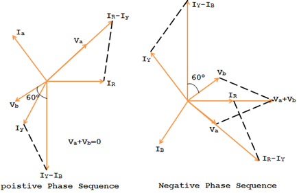
The negative sequence relay has the inverse square law characteristic. i.e., I22t = K, a constant. I2 is the negative sequence component of the current.
t = K / I22 i.e., t α 1/I22.
The relay will trip the generator’s main breaker.
