
The Marvellous World of Induction-Type Reactance Relays
Induction Type Reactance Relay Operation

Fundamental Principles
Induction-type reactance relays are designed to respond to specific operating quantities within a power system, often current or voltage. They rely on the interaction between magnetic fields and electric currents, capitalizing on the phenomenon of electromagnetic induction. This interaction generates torques that determine the relay’s response.
Structural Configuration
In a simplified configuration known as the “Induction Cup,” the relay comprises upper, lower, and right-hand side poles. The primary winding is typically connected to the power circuit, while the secondary winding, closed by a phase-shifting course, is positioned on the right-hand side pole. This secondary winding introduces a phase shift, causing the flux in the right-hand side pole to be out of phase with the change in the upper and lower bars.
Operating Torque Generation
The phase difference between the magnetic fluxes is the key to the relay’s operation. When current flows through the primary winding, it generates magnetic fluxes in all the poles. The interaction between the flux in the right-hand side pole and the polarizing flux results in an operating torque denoted as K1I^2, where I represent the current flowing through the primary winding. This torque serves as the driving force for the relay’s response.
Restraint Mechanism
While the operating torque initiates the relay’s response to a fault or abnormal condition, a restraining mechanism ensures stability during normal operations. The interaction between the left-hand side pole and the polarizing flux generates a restraining torque. This torque counteracts the operating torque, preventing unnecessary tripping when operating within acceptable parameters.
Phase Angle Adjustment
A phase angle adjustment circuit is introduced to tailor the relay’s response to specific protection requirements. This circuit is connected in series with the voltage coil, enabling adjustments to the relay’s sensitivity and response characteristics. By modifying the phase angle, the relay’s behavior can be fine-tuned to detect faults while minimizing false trips accurately.
R-X Diagram of Induction Type Reactance Relay
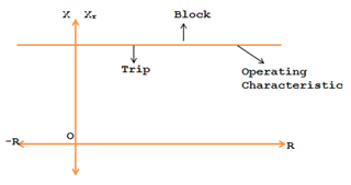
As the value of K3 is very small, it can be neglected.
Reactance Relay Operation & Application

The reactance relay will operate when the measured value of the reactance is less than the predetermined or designed value of K.
The directional unit used with the reactance relay is not the same as the one used with the impedance type relay because the reactance relay will trip under normal load conditions when the power factor of the load is unity or near zero. This is because; the restraining reactive volt-ampere at U.P.F. or near U.P.F. will be near zero. Therefore, we must have a directional unit called the Mho unit or Mho relay, having a circular characteristic.
Reactance relays protect short lines with fault currents less than 20 K.A. In such lines, the effect of fault resistance or arc resistance is predominant.
Understanding the Axes
The 2R-X diagram has two main axes: the horizontal axis represents the real part of the impedance (R), while the vertical axis represents the reactive part of the impedance (X). Each point on the diagram corresponds to a specific combination of resistance and reactance in the system.
Relay Zone and Characteristics
In the 2R-X diagram, the relay’s operation is divided into zones corresponding to different faults and operating conditions. These zones help classify the behavior of the relay and understand how it responds to various situations:
- This is the region where the relay operates when a fault occurs. The relay’s settings and characteristics define it. When the impedance of the faulted circuit falls within this zone, the relay initiates a protective action.
- This zone represents the area where the relay does not operate. The impedance values in this zone are typically beyond the relay’s sensitivity settings. It ensures the relay remains stable and does not trip during normal operating conditions.
Application and Analysis
Engineers use the 2R-X diagram to analyze the relay’s response to various fault conditions. By plotting the impedance of the faulted circuit on the chart, they can determine whether the relay will trip or remain inactive. This analysis aids in setting the relay’s parameters correctly for the desired level of protection and selectivity.
Considerations
- Coordination: The 2R-X diagram is crucial for relay coordination within a network. It ensures that relays closest to the fault operate while allowing more distant relays to remain inactive.
- Fault Analysis: Engineers can use the diagram to study fault conditions and identify potential issues within the network that may affect the relay’s performance.
- System Changes: If the network configuration changes, the 2R-X diagram might need to be adjusted to reflect the new conditions and maintain proper protection coordination.
Reactance Relay With MHO Starter
For first, second, and third zone protection of the transmission line, reactance relays as employs for 1st and 2nd zones. The directional unit, a mho starter relay, acts as 3rd zone protective relay.
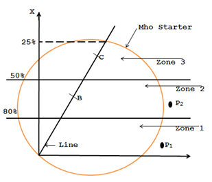
The directional unit used with the reactance relay, viz. mho starter, has a circular characteristic because of the reason explained below:
High Power Factor Loads
During normal conditions with high power factor loads, the measured reactance by the relay might fall below its set value. This situation could lead to false tripping if not appropriately addressed.
Zone Segmentation
To ensure that the relay operates accurately and selectively, it is necessary to supervise its operation. This supervision is achieved by limiting the relay’s area on the R-X (reactance-resistance) diagram.
Circular Supervision & 3rd Zone
Under normal conditions, with a load of high power factor, the reactance measured by the relay may be less than its setting. P1 and P2 in the diagram lie in zones 1 and 2, respectively. To prevent false tripping under such conditions, the reactance relay should be supervised by a fault-detecting unit (starting unit or starter), which limits its area on the R-X diagram. Hence its characteristic should be circular. The forming unit detects fault and also serves the function of the 3rd zone unit.
Understanding the Need for Precision
In power systems, high power factor loads are common. However, these loads can distort the reactance measurements of a relay, potentially leading to false tripping. The reactance relay, designed to respond to specific impedance levels, might trigger protective actions inaccurately in such scenarios.
Advantages
The amalgamation of the reactance relay with the MHO starter offers noteworthy advantages:
- False Tripping Prevention: The MHO starter maintains the system’s stability and prevents unwarranted disruptions by preventing the relay from falsely tripping due to a high power factor.
- Unified Protection: The circular MHO starter considers reactive and resistive elements, ensuring uniform protection across a spectrum of fault conditions. This feature enhances the overall reliability of fault detection.
- Extended Coverage: Beyond addressing false tripping, the MHO starter is a third zone unit. This expansion of protection coverage adds a layer of security to the power network.
Conclusion
As we conclude our journey through the captivating world of induction-type reactance relays, we find ourselves at the intersection of tradition and innovation, where the elegance of electromagnetic principles meets cutting-edge engineering. These relays, operating as guardians of stability within electrical networks, exemplify the harmonious synergy between scientific theory and practical application.
