

Half Wave and Full Wave Rectifier: A Comprehensive Guide
When you start exploring rectifiers, you’ll compare half-wave and full-wave types. It’s fascinating how these devices differ in efficiency and design while converting AC to DC. A half-wave rectifier uses only a single diode, making it simple and cost-effective but inefficient. Contrast that with the full wave rectifier, which cleverly utilizes both halves of the AC cycle, providing a smoother output. But what sets them apart when considering the ripple factor and real-world applications? Let’s explore how these differences impact their performance and usefulness. Learn more about Half Wave and Full Wave Rectifier.
Key Takeaways
- Half-wave rectifiers use a single diode, converting only one-half of the AC cycle to DC.
- Full-wave rectifiers utilize AC cycle halves for higher efficiency and smoother DC output.
- Bridge rectifiers, a type of full-wave rectifier, use four diodes, enhancing performance without needing a center-tapped transformer.
- Full-wave rectifiers have lower ripple and higher efficiency compared to half-wave rectifiers.
- Filter capacitors are used in both rectifiers to reduce ripple and stabilize the DC output.
Rectifier Basics

Plunge into the world of rectifiers, where diodes make the transformation of alternating current (AC) to direct current (DC) possible. As you explore this fascinating technology, you’ll discover how rectifiers convert AC voltage into DC voltage, essential in countless electronic applications. Diodes, the cornerstone of these circuits, allow current to flow in only one direction, effectively transforming AC’s bidirectional wave into a unidirectional DC flow.
Rectifiers can be broadly categorized into two types based on their functionality: half-wave and full-wave. A half-wave rectifier uses just one-half of the AC cycle, which only allows the positive or negative half of the wave to pass through the diode. This method results in a DC output with higher ripple and lower efficiency.
On the other hand, a full-wave rectifier capitalizes on both halves of the AC cycle. A transformer and additional diodes produce a smoother DC output with significantly reduced ripple and enhanced efficiency. By understanding these distinctions, you can better appreciate rectifiers’ roles in electronic circuits.
Half Wave Rectifier Overview
When you work with a half-wave rectifier, you convert only one-half of the AC input cycle into a usable DC output with the help of a single diode. This setup is simpler and more cost-effective, but it comes with limitations like a higher ripple factor and inefficient conversion during the negative half cycle. Understanding these trade-offs is essential for deciding if a half-wave rectifier meets your project’s needs.
Basic Operation Explained
The basic operation in a half-wave rectifier involves converting only half of the alternating current (AC) input cycle into direct current (DC) output. You’ll see that half-wave rectifiers use a single diode to facilitate this conversion. During the positive half cycle, the p-n junction diode conducts, allowing current to flow and creating a pulsating DC output. This is a key difference from full wave rectifiers, which utilize multiple diodes to process both halves of the AC cycle.
When examining rectifier circuits, you’ll notice the output waveform of a half-wave rectifier consists of a series of positive pulses. This pulsating nature leads to a higher ripple factor than full-wave rectifiers, meaning the DC output voltage isn’t as smooth.
Despite this, half-wave rectifiers are often appreciated for their simplicity and cost-effectiveness.
However, half-wave rectifiers’ rectification efficiency is lower when only one-half of the AC cycle is utilized. This results in increased power loss and lower overall efficiency. Understanding this basic operation helps you appreciate how these rectifiers convert AC to DC, even though they have certain limitations.
Key Advantages and Limitations
Having grasped the basic operation of half-wave rectifiers, weighing their key advantages and limitations is important. Half-wave rectifiers stand out for their simplicity and cost-effectiveness. You only need a single diode and a load resistor, making them easy to implement when working with limited resources. However, they only rectify one-half of the AC input cycle, resulting in a pulsating DC output that isn’t as smooth as you might like.
Advantages and Limitations of Half Wave Rectifiers
| Advantages | Limitations |
|---|---|
| Cost-effective | Higher ripple |
| Simple design | Lower efficiency |
| Minimal components (one diode) | More harmonics in the output |
| Suitable for low-power applications | Only one-half of the input cycle is used |
| Easy to implement | Output current is not constant |
A half-wave rectifier’s efficiency is significantly lower than a full-wave rectifier’s, and the output current has a significant ripple. This ripple can increase harmonics, potentially causing issues in sensitive electronic applications. Consider these limitations carefully if you need a consistent DC supply for your load. Despite these drawbacks, half-wave rectifiers can still be the right choice for simple, low-power applications where cost and simplicity are key factors.
Full Wave Rectifier Overview

When you explore full-wave rectifiers, you’ll notice they consist of two power diodes connected to a single load resistance. This setup allows the rectifier to conduct during both positive and negative half cycles, doubling the average DC output voltage compared to a half-wave rectifier.
You’ll also appreciate that full wave rectifiers don’t need a center-tapped transformer and provide a smoother output.
Diode Configuration Types
A full wave rectifier, particularly in its bridge configuration, cleverly uses four diodes to convert alternating current (AC) to direct current (DC) without requiring a center-tapped transformer. This setup, known as the bridge rectifier setup, is a preferred diode configuration for achieving full-wave rectification. By utilizing both halves of the AC input cycle, bridge rectifiers guarantee a smooth DC output. This efficient approach provides higher efficiency than half-wave rectifiers, making it ideal for applications requiring minimal ripple and stable DC output.
Here’s a quick breakdown of why the bridge rectifier setup is advantageous:
- Diode Configuration: This configuration uses four diodes arranged in a closed-loop configuration, allowing current to flow during both halves of the AC cycle.
- No Center-Tapped Transformer Needed: The lack of a center-tapped transformer simplifies the design and reduces costs.
- Full-Wave Rectification: Converts both positive and negative halves of the AC input cycle, improving efficiency.
- Smooth DC Output results in a more stable and continuous DC current with less ripple than half-wave rectification.
Output Voltage Characteristics
One might wonder why full-wave rectifiers are favored for their output voltage characteristics. It’s simple: they outperform half-wave rectifiers by providing a higher average DC output voltage. When you’re dealing with AC to DC conversion, the efficiency of a full wave rectifier becomes evident.
This rectifier circuit takes advantage of both halves of the AC input cycle, resulting in a more constant and steady output waveform. This translates to a smoother DC output, essential for power supply applications.
The bridge rectifier, a common type of full-wave rectifier, reduces the ripple factor. A lower ripple factor means that the DC output voltage is less varied, enhancing the quality of the power supply.
While a half-wave rectifier only uses one-half of the AC cycle, leading to a choppier and less efficient output, the full-wave rectifier provides a more efficient solution. This increased AC-to-DC conversion efficiency makes it ideal for reliable and stable power applications.
Output Waveform Analysis
Analyzing the output waveform of rectifiers is crucial in comprehending their performance and efficiency. When you delve into the output waveform analysis of half-wave and full-wave rectifiers, you’ll observe significant differences that affect rectifier performance.
A half-wave rectifier circuit only uses one portion of the AC cycle, resulting in a DC output waveform with a higher ripple frequency and a lower average output voltage. This results in heightened ripple and reduced efficiency compared to its full-wave counterparts.
In contrast, a full-wave rectifier circuit, like a bridge rectifier, utilizes both segments of the AC cycle. This yields a more seamless DC output waveform and a higher average output voltage, diminishing the ripple frequency. Here’s what you should consider:
- Half-wave rectifier circuit: This circuit processes solely half of the AC cycle, resulting in a DC output with increased ripple and decreased voltage.
- Full-wave rectifier circuit: Makes use of the entire AC cycle, providing a smoother output and enhanced efficiency.
- Bridge rectifier: A typical full-wave configuration offering excellent performance.
- Efficiency comparison: Full-wave rectifiers excel in reducing ripple and increasing output voltage compared to half-wave rectifiers.
Efficiency and Performance
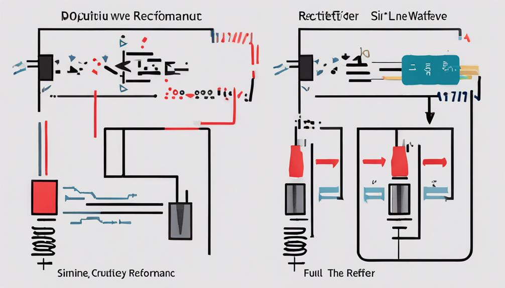
Full-wave rectifiers outperform their half-wave counterparts by a large margin in efficiency and performance. They greatly enhance power conversion efficiency by utilizing both halves of the AC cycle. This results in smoother DC output, characterized by a lower ripple factor and higher average output voltage. Such improvements mean a more stable and reliable performance for your electronic devices.
In contrast, half-wave rectifiers, which only use one-half of the AC cycle, have a higher ripple factor and lower efficiency. This leads to more fluctuations in the output waveform, which can impact the overall rectifier performance. To evaluate these differences, analyzing output waveforms is necessary. You’ll notice that full-wave rectifiers deliver a more consistent and dependable output.
Selecting the right diodes with appropriate PIV ratings for your rectifier is vital. Engineers aim to optimize rectifier performance by reducing the ripple factor and selecting efficient components. By focusing on these aspects, you can guarantee a superior power conversion process and achieve better efficiency.
PIV and Ripple Factor
Understanding peak inverse voltage (PIV) and ripple factors is essential to designing successful rectifier circuits. PIV is pivotal when selecting diodes for rectifier circuits because it determines the maximum reverse voltage they can handle without breaking down. This means choosing diodes with appropriate PIV ratings is necessary to guarantee the reliability of both half-wave and full-wave rectifiers.
Conversely, the Ripple factor measures the fluctuations in your rectified DC output. Lower ripple factors indicate a smoother and more stable output, which is desirable for efficient rectifier circuits. Here’s how you can optimize your rectifier performance:
- Select Diodes with Proper PIV Ratings: Ensure the diodes can safely handle the reverse voltage in the circuit.
- Use Full-Wave Rectifiers. They typically have a lower ripple factor than half-wave rectifiers, leading to better ripple reduction.
- Aim for Lower Ripple Factor: Achieve a smoother rectified DC output by minimizing fluctuations.
- Focus on Efficiency: Balance between PIV ratings and ripple reduction for the most efficient rectifier circuits.
Filtering Techniques

Having grasped the importance of PIV and ripple factor in rectifier design, let’s explore filtering methods to enhance your circuit’s performance.
In rectifier circuits, filter capacitors are vital in reducing ripple voltage. Doing so helps guarantee the output voltage remains as stable as possible. The rectified waveform naturally exhibits peaks and valleys, but smoothing capacitors come to the rescue by storing energy during these peaks and releasing it during the valleys. This energy transfer minimizes fluctuations and enhances output stability.
When it comes to filtering methods, proper capacitor sizing is crucial.
The effectiveness of a filter capacitor greatly relies on its value. A capacitor that’s too small won’t adequately smooth out the ripple voltage, leading to larger fluctuations in the output voltage. Conversely, an oversized capacitor might be unnecessary and costly. Thus, carefully selecting the right capacitor size is key to achieving a steady DC output.
Real-World Applications
You’ll find rectifiers at the heart of countless devices, transforming AC into DC to power our electronic world. Full-wave rectifiers, especially bridge rectifiers, are essential in power supply applications due to their efficiency and ability to provide a smoother DC output. They excel in converting AC to DC for electronic devices, ensuring a reliable DC power supply. These rectifier circuits are necessary for various applications, from small gadgets to industrial machinery.
Here’s where you’ll see rectifiers in action:
- Welding Machines: Full-wave rectifiers deliver steady, polarized DC voltage, which is important for welding operations.
- Household Appliances: Bridge rectifiers convert high AC voltage to low DC voltage, powering electronic components efficiently.
- Battery Chargers and Solar Panels facilitate AC to DC conversion, charging batteries, and harnessing solar energy effectively.
- Electric Vehicles: Rectifiers are key in converting AC input to DC load required for vehicle batteries.
The transformer utilization factor and ripple reduction are significant in these applications, ensuring efficient performance.
Rectifier components are meticulously designed to meet the demands of various DC power supply needs, emphasizing reliability and efficiency in every application.
Conclusion
You’ve explored the essentials of half-wave and full-wave rectifiers, understanding their differences and applications. Half-wave rectifiers are simple and cost-effective but inefficient, making them less suitable for stable DC needs. In contrast, full-wave rectifiers, especially in bridge configurations, offer smoother outputs with less ripple, ensuring better performance and efficiency. Choosing the right rectifier type can optimize power conversion in your projects, providing reliable and efficient operation.
FAQs
1. What Is the Difference Between a Wave and a Wave Rectifier?
You compare rectifier operation by evaluating voltage output, current flow, and diode function. Full wave uses more diodes, offering a smoother waveform shape, lower ripple voltage, and better efficiency. Transformer usage affects power dissipation and the rectification process.
2. What Is a Half Wave Rectifier?
You use a half-wave rectifier to convert AC signals into pulsating DC. Its diode functionality allows current flow during the positive input waveform, creating an output waveform with peak voltage but a higher ripple factor and lower efficiency.
3. What Is a Full-Wave Rectifier?
You’re exploring full-wave rectifiers, which use diode operation to transform AC input into DC output. They utilize a bridge circuit or transformer, reducing ripple voltage and enhancing efficiency compared to half-wave rectifiers. Manage peak inverse voltage for the best power supply.
4. Are Full Wave Rectifiers More Efficient Than Half Wave?
Full-wave rectifiers excel in efficiency comparisons. They minimize power loss, handle peak voltage better, and reduce ripple factor. By optimizing transformer utilization and diode arrangement, they improve the rectification process, voltage regulation, and output waveform despite circuit complexity.
