

Exploring the Factors Affecting Electrical Resistance
Length of the material

The resistance of a material is directly influenced by its length, as stated by one of the fundamental principles of electrical engineering, known as the “resistance-length relationship.” This relationship is a key aspect of Ohm’s Law, which describes how current, voltage, and resistance are interconnected in an electrical circuit.
The resistance-length relationship can be explained using the following points:
Direct Proportionality
The resistance of a conductor is directly proportional to its length. This means that as the length of a conductor increases, its resistance factors also increase, assuming all other factors remain constant. Conversely, if the size of the conductor is decreased, the resistance decreases as well.
Electron Flow
When an electric current flows through a conductor, it involves the movement of electrons. These electrons experience collisions with the atoms of the material as they move. In a longer conductor, electrons have to travel a greater distance and thus experience more crashes, which increases the overall opposition to their movement, leading to higher resistance.
Resistivity and Length
The resistance of a material is also influenced by its resistivity (ρ), an intrinsic property of the material. The resistance of a conductor can be calculated using the formula R = ρ * (L / A), where R is resistance, ρ is resistivity, L is length, and A is the cross-sectional area. This formula highlights the direct relationship between resistance and size.
Units and Measurement
The SI resistance factors unit is the ohm (Ω). Suppose the length of a conductor is measured in meters (m), and the cross-sectional area is measured in square meters (m²). In that case, the resistance can be directly determined using the formula above.
Applications
Understanding the resistance-length relationship is crucial in various practical applications. For instance, engineers consider the length of wires and conductors when designing electrical circuits to ensure the resistance remains within acceptable limits. In high-power applications, minimizing the size of conductors helps reduce energy losses due to heat generated by resistance.
Voltage Drop
A longer conductor can lead to a higher voltage drop across it when carrying a current. This voltage drop can affect the performance of electrical devices and may require compensation or adjustments in circuit design.
Charge and the electric current

Electric current is the flow of electric charge through a conductor, and it plays a fundamental role in the world of electricity and electronics. Charge, the whole property of matter responsible for electrical interactions, can be positive (protons) or negative (electrons). When a charge is in motion, it constitutes an electric current. This movement can be compared to water flow in a river, where the water molecules represent the charges.
Charge
Charge is a fundamental property of matter, and it can be either positive or negative. In an atom, protons carry a positive charge, electrons have a negative charge, and neutrons are neutral. Charges exert electromagnetic forces on each other, attracting (opposite charges) or repelling (like charges) one another.
Electric Current
Electric current is the flow of electric charge through a conductor. It is measured in amperes (A) and represents the rate controls move. Current can flow in two forms: direct current (DC), where charges flow steadily in one direction, and alternating current (AC), where costs periodically reverse their flow direction.
Resistance
Resistance is the opposition electric charges encounter as they move through a conductor. It’s measured in ohms (Ω). Resistance hinders the flow of orders and transforms some of their kinetic energy into heat. Conductors with low resistance allow current to flow more easily, while materials with high resistance impede the flow.
Ohm’s Law
Ohm’s Law, named after the German physicist Georg Simon Ohm, relates these three concepts: electric current (I), voltage (V), and resistance (R). This is mathematically expressed as V = I * R, where V is voltage, I is current, and R is resistance. This equation reveals that the voltage across a conductor is directly proportional to the recent passing through it and the resistance it offers.
Relationship Between Current and Resistance
According to Ohm’s Law, the current passing through a conductor is directly proportional to the voltage applied and inversely proportional to its resistance. This means that an increase in voltage leads to a higher current, while an increase in resistance reduces the wind for a given voltage.
Impacts
- Heat Generation: Resistance causes energy to be dissipated as heat when current flows through a conductor. This effect is utilized in heating elements, such as toasters and electric stoves.
- Voltage Drop: A voltage drop occurs across components with resistance in a circuit. This can affect the performance of devices by reducing the voltage available to them.
- Power Loss: Resistance leads to power loss in electrical systems. The greater the resistance, the more power is lost as heat, which can be a concern in high-power applications.
- Circuit Design: Engineers must consider when designing circuits to ensure that components receive the necessary current and voltage for proper operation.
Temperature
Electric potential and potential difference

Electric potential, often referred to as “potential,” is a scalar quantity that describes the electric potential energy per unit charge at a point in space due to the presence of an electric field. It represents the work needed to move a positive test charge from infinity to a specific topic within the electric field.
Mathematically, electric potential (V) at a point is given by the equation:
Where,
- Is the electric potential at the moment?
- Is the electric potential energy associated with the point charge?
- Is the magnitude of the test charge.
The SI unit of electric potential is the volt (V).
Potential Difference (Voltage)
The potential difference, often referred to as “voltage,” is the difference in electric potential between two points in an electric field. It quantifies the work done per unit charge moving a head between those two points.
Mathematically, the potential difference (AB) between point A and point B is given by:
AB=
Where,
- AB is the potential difference between points A and B.
- is the electric potential at point B.
- is the electric potential at point A.
The SI unit of potential difference is also the volt (V).
Key Points
- Electric potential is a property of a point in space and describes how much electric potential energy a unit positive charge would have at that point.
- The potential difference (voltage) between two points is the work done per unit charge moving a head between those points. It’s a measure of the energy difference per unit charge.
- Voltage is the driving force that causes charges to move through a circuit. It’s responsible for the flow of electric current.
- In a uniform electric field, the potential difference between two points is directly proportional to the distance between those points.
- Positive charges move from higher potential to lower potential (lower voltage) to reduce their potential energy, while negative charges move in the opposite direction.
- The concept of potential difference is crucial in understanding circuits, electrical power distribution, and various electrical devices.
- In a circuit, voltage sources (such as batteries) create potential differences that drive current flow through components.
Temperature Effects
- Temperature Coefficient
- Atomic Vibrations
- Thermistors
Temperature Coefficient
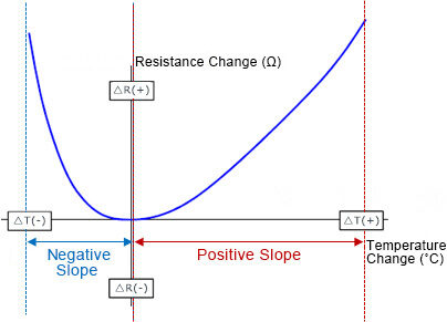
Different materials exhibit varying responses to temperature changes, leading to positive or negative TCR values. A positive TCR indicates that resistance increases with temperature, while a negative TCR signifies that resistance decreases as temperature rises. This distinction has significant implications for practical applications. Explain how the TCR is calculated using the formula TCR = (Rt – R0) / (R0 × ΔT), where Rt is the resistance at temperature t, R0 is the at the reference temperature, and ΔT is the temperature difference between t and the reference temperature. Provide examples of typical TCR values for common materials, such as copper (approximately +0.0039 Ω/°C) and silicon (approximately -0.075 Ω/°C).
Atomic Vibrations
Atoms within a material are not static; they are in a constant state of motion due to their thermal energy. Atomic vibrations occur as particles oscillate around their equilibrium positions. These vibrations can be classified as either longitudinal (parallel to the direction of wave propagation) or transverse (perpendicular to the direction of wave propagation). Atomic vibrations impact conductors and insulators differently. In conductors, the movement of charge carriers (electrons) is already relatively free, and atomic vibrations mainly cause scattering events. This scattering increases resistance in conductors as the temperature rises. In insulators, where electrons are tightly bound to atoms, atomic vibrations affect electron mobility, resulting in changes in resistivity.
Thermistors
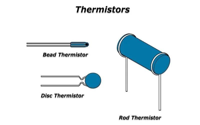
Thermistors are typically made of semiconductor materials, such as metal oxides or polymers, with a negative temperature coefficient of resistance (NTC) or positive temperature coefficient of resistance (PTC). NTC thermistors exhibit a decrease in resistance as temperature rises, while PTC thermistors show an increase with increasing temperature. The temperature relationship in thermistors arises from the changes in the concentration of charge carriers (either electrons or holes) as temperature changes. In NTC thermistors, as the temperature increases, more charge carriers are available for conduction, resulting in a decrease in resistance. PTC thermistors work on the principle of positive temperature coefficient materials, where the resistance increases due to the reduction in charge carrier concentration with temperature.
Conclusion
By understanding these factors, we can manipulate and optimize resistance in our designs. Whether selecting the most suitable materials for specific applications, considering the impact of temperature on circuit performance, or designing precise contact points to minimize, our knowledge empowers us to create more efficient and reliable systems.
