

Explanation of Thevenin’s Theorem
Statement of Thevenin’s Theorem
Explanation of Thevenin’s Theorem
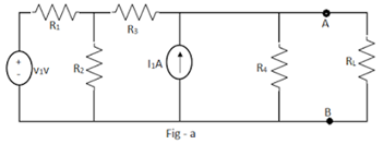
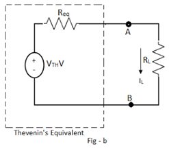
The theory of Thevenin’s equivalent across the terminals of interest can be explained by considering the circuit shown in Fig-a. Terminals A-B are the terminals of interest across which RL is connected. Then Thevenin’s equivalent across the load terminals A-B can be obtained as shown in Fig-b.
Superposition Theorem
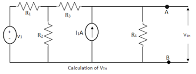
While obtaining VTH, any of the network simplification techniques can be used. When the circuit is replaced by Thevenin’s equivalent across the load resistance, then the load current can be obtained as
By using this theorem, current through any branch of the circuit can be obtained, treating that branch resistance as the load resistance and getting Thevenin’s equivalent across the two terminals of that branch resistance as the load resistance and getting Thevenins equivalent across the two terminals of the branch.
Steps to Apply Thevenin’s Theorem
-
Remove the branch resistance through which the current is to be calculated.
-
Calculate the voltage across these open-circuited terminals using any network simplification technique. This is VTH.
-
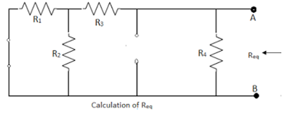
Calculate Req as viewed through the two terminals of the branch from which current is calculated by removing that branch resistance and replacing all independent sources with their internal resistances. If the internal resistances are unknown, replace Independent voltage sources with short circuits and independent current sources with open courses.
-
Draw the Thevenin’s equivalent showing source VTH, with the resistance Req in series, across the terminals of a branch of interest.
-
Reconnect the branch resistance. Let it be RL. The required current through the branch is given by,
Limitations of Thevenin’s Theorem
-
Not applicable to circuits consisting of nonlinear elements.
-
Not applicable to unilateral networks.
-
There should not be magnetic coupling between the load and circuit to be replaced by Thevenin’s theorem.
-
Controlled sources on the load side should not be controlled from another part of the circuit.
