

Demystifying the EMF Equation of a DC Generator
When it comes to understanding the inner workings of a DC generator, one of the fundamental concepts that engineers and enthusiasts need to grasp is the EMF equation. A DC generator’s EMF (Electromotive Force) equation is a critical component that governs its operation and efficiency. In this comprehensive guide, we will delve deep into a DC generator’s EMF equation, providing detailed derivation, examples, and practical insights.
Understanding the Basics
Before we dive into the derivation and examples, let’s establish a solid foundation by exploring the basics of a DC generator’s EMF equation.
What is the EMF Equation of a DC Generator?
The EMF equation of a DC generator is a mathematical expression that quantifies the electromotive force generated within the generator. Understanding how voltage is produced and maintained in a DC generator is essential. This equation is fundamental in designing and analyzing DC generators for various applications.
Derivation of the EMF Equation
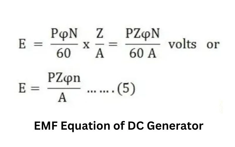
Now, let’s explore the derivation of the EMF equation of a DC generator. We’ll break it down step by step to make it more accessible.
Step 1: Faraday’s Law of Electromagnetic Induction
The foundation of the EMF equation lies in Faraday’s Law of Electromagnetic Induction, which states that the electromotive force (EMF) induced in a closed loop is directly proportional to the rate of change of magnetic flux through the loop. Mathematically, it can be expressed as:

Where:
- E = Electromotive Force (EMF)
- N = Number of Turns in the Coil
- = Rate of Change of Magnetic Flux
Step 2: Understanding Magnetic Flux
To apply Faraday’s law to a DC generator, we must define magnetic flux (Φ). Magnetic flux is the product of the magnetic field strength (B) and the area (A) through which the magnetic field lines pass, and the formula gives it:
Where:
- = Magnetic Flux
- B = Magnetic Field Strength
- A = Area
Step 3: Deriving the EMF Equation for a DC Generator
In a DC generator, a coil or armature rotates within a magnetic field, causing a change in magnetic flux. This change in magnetic flux induces an EMF in the coil. To derive the EMF equation for a DC generator, we need to consider the number of turns in the coil (N), the angular velocity (ω) of the coil’s rotation, and the angle (θ) between the magnetic field lines and the normal to the coil. The EMF equation is given by:
Where:
- E = Electromotive Force (EMF)
- N = Number of Turns in the Coil
- B = Magnetic Field Strength
- A = Area of the Coil
- = Angular Velocity of the Coil
- = Angle between the Magnetic Field Lines and the Normal to the Coil
Practical Examples
Let’s explore some practical examples to understand better how the EMF equation works in real-world scenarios.
Example 1: Simple DC Generator
Consider a simple DC generator with 100 turns in the coil, a magnetic field strength of 0.2 Tesla, an area of 0.02 square meters, and an angular velocity of 1000 radians per second. If the angle is 30 degrees, calculate the induced EMF.
Using the EMF equation:
E = 200 Volts
In this example, the induced EMF is 200 Volts.
Example 2: Multiple Coils
Multiple coils are often arranged in different configurations in more complex DC generators. To calculate the total induced EMF, you would sum the EMFs of all the individual coils using the EMF equation.
Further Applications and Considerations
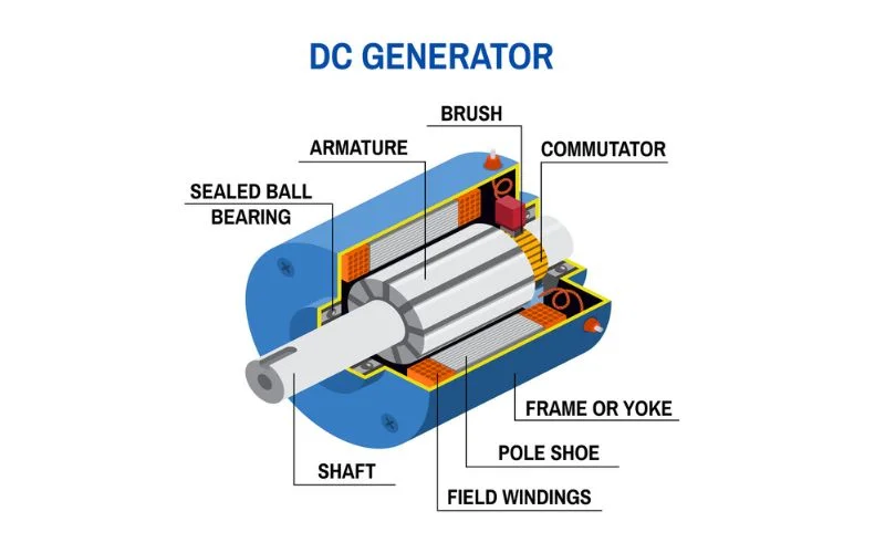
Now that we have a solid grasp of the EMF equation for DC generators let’s explore some practical applications and considerations that engineers and researchers encounter in the field.
Application 1: Generator Efficiency
Efficiency is a critical factor when designing and operating DC generators. The efficiency (η) of a generator is defined as the ratio of the electrical power output (P_out) to the mechanical power input (P_in). Mathematically, it can be expressed as:
Efficiency is a key performance parameter, and optimizing it ensures that the generator operates with minimal losses, making it more energy-efficient.
Application 2: Voltage Regulation
Voltage regulation is another crucial aspect of DC generators. It refers to the ability of the generator to maintain a relatively constant output voltage under varying load conditions. Voltage regulation is typically expressed as a percentage and can be calculated using the following formula:
Where:
- V_no-load = Output voltage under no-load conditions
- V_full-load = Output voltage under full-load conditions
Consideration 1: Commutation
In DC generators, commutation reverses the direction of current flow in the armature coil as it rotates within the magnetic field. Proper commutation ensures the generated voltage remains in the desired polarity. Issues with commutation can lead to sparking, damaging the generator and reducing its efficiency.
Consideration 2: Brushless DC Generators
While traditional DC generators use brushes and a commutator to transfer electrical power from the rotating armature to the external circuit, brushless DC generators have recently gained popularity. Brushless generators use electronic circuits and magnets to eliminate the need for brushes and commutators, reducing maintenance and improving reliability.
FAQs
What factors can affect the induced EMF in a DC generator?
Several factors can affect the induced EMF in a DC generator, including the number of turns in the coil, the strength of the magnetic field, the area of the coil, the angular velocity of rotation, and the angle between the magnetic field lines and the coil.
Is the EMF equation the same for all types of DC generators?
The basic EMF equation is the same for all DC generators. However, depending on the generator’s design and intended use, variations and additional factors may be considered in practical applications.
How can I increase the output voltage of a DC generator?
To increase the output voltage of a DC generator, you can increase the number of turns in the coil, strengthen the magnetic field, increase the area of the coil, increase the angular velocity of rotation, or change the angle between the coil and the magnetic field lines.
Conclusion
Understanding the EMF equation of a DC generator is crucial for anyone working with electrical systems. It is the foundation for designing, analyzing, and optimizing these generators for various applications. By mastering the derivation and examples provided in this guide, you’ll be well-equipped to tackle the challenges of DC generator technology and harness its potential for your projects.
