

Demystifying the Construction of Three-Phase Induction Motors
Regarding industrial applications and powering heavy machinery, the three-phase induction motor is a cornerstone of modern engineering. This remarkable machinery is a workhorse in many industries, from manufacturing to agriculture. In this article, we will delve into the construction of a three-phase induction motor, uncovering the intricate details that make it a marvel of electrical engineering.
Understanding Three-Phase Induction Motors
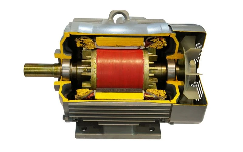
Before we dive into the construction details, let’s first grasp the basics of a three-phase induction motor.
What is a Three-Phase Induction Motor?
A three-phase induction motor, often called an induction motor, is a type of electric motor used to convert electrical energy into mechanical energy. It operates on the principle of electromagnetic induction, where a rotating magnetic field is created within the motor to induce the rotation of a rotor. These motors are widely used for their simplicity, reliability, and efficiency.
Key Features of Three-Phase Induction Motors
Three-phase induction motors come with several key features:
- Stator: The stator is the stationary part of the motor and consists of laminated iron cores and windings. It generates a rotating magnetic field with three-phase alternating current (AC) power.
- Rotor: The rotor is the rotating part of the motor. It is made up of either a squirrel cage or wound rotor construction. The rotor interacts with the rotating magnetic field, resulting in mechanical rotation.
- Bearings: Induction motors are equipped with bearings to support the rotor and reduce friction during rotation.
Now that we have a basic understanding let’s explore the intricate construction of a three-phase induction motor.
Construction of Three Phase Induction Motor
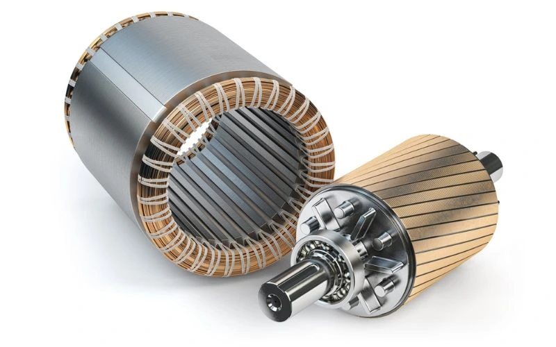
A three-phase induction motor comprises several crucial components working together seamlessly to produce mechanical motion. Let’s break down its construction step by step.
Stator
It contains a steel frame surrounding a hollow cylindrical-shaped core of thin silicon steel laminations to reduce hysteresis and eddy current loss. Aerial equally spaced slots are provided on the inner bound of the laminations. The insulation is connected to arrange a balanced three-phase star or delta-connected circuit. The three-phase stator coil is wound for a particular no. of poles as per the necessity of speed. If the number of bars is more, then the motor speed is less, and vice-versa. A rotating magnetic field with perpetual magnitude is developed once a three-phase supply is supplied to the Stator winding. This rotating magnetic field makes currents within the rotor due to electromagnetic induction.
The stator is the heart of the induction motor. It consists of the following elements:
- Stator Core: Typically made of laminated steel sheets, the stator core provides a low reluctance path for the magnetic flux generated by the stator windings.
- Stator Windings: These windings are carefully arranged in slots on the stator core. When three-phase AC power is applied, it generates a rotating magnetic field that surrounds the rotor.
Rotor
Squirrel Cage Rotor Type
It contains a laminated cylindrical is-shaped core having parallel slots on the outside boundary. Either an aluminium bar or copper bar is fixed in each place. All these bars are joined with metal rings termed end rings at one end. This arrangement permanently makes short-circuited winding, which is everlasting. There will not be any electrical supply to the rotor, but the current will be induced because of transformer action from the Stator.
Thus, the induction motor that uses the squirrel cage rotor is named the squirrel cage induction motor. Its simple and robust construction advantage enables it to operate in the most adverse situations. On the other hand, it has the disadvantage of a low starting torque. This is due to permanently short-circuited rotor bars. To have a high starting torque, it is not possible to add resistance externally.
Wound Rotor Type

At the starting period, the external resistances are engaged to have a high starting torque. Once the motor reaches its rated speed, the wound rotor runs similarly to the squirrel cage rotor by short-circuiting the three brushes.
Bearings
Bearings support the rotor’s weight and facilitate its smooth rotation. The choice of bearings depends on factors such as motor size and application.
Housing and Cooling
The motor components are enclosed in a sturdy housing to protect them from environmental factors and provide structural integrity. Adequate cooling, often achieved through fans or other cooling mechanisms, is essential to maintain motor efficiency and prevent overheating.
Terminal Box
A terminal box is provided for connecting the motor to the power supply and controlling devices. It contains terminals for the motor leads and may include protective features like overload relays and thermal sensors.
Why is Understanding the Construction Important?

Understanding the construction of a three-phase induction motor is vital for various reasons:
- Maintenance: Knowledge of the motor’s construction aids in proper maintenance and troubleshooting, helping to diagnose and rectify issues efficiently.
- Optimization: Understanding the motor’s components allows for optimizing its performance for specific applications, such as adjusting rotor resistance for better control.
- Safety: Knowing the motor’s construction is essential for ensuring the safety of personnel working with or near the motor.
Conclusion
FAQs
Can a three-phase motor be operated on a single-phase supply?
No, a three-phase induction motor is designed to work with a three-phase power supply. Attempting to run it on a single-phase supply will result in reduced performance and potential damage to the motor.
What are the advantages of a squirrel-cage rotor over a wound rotor?
A squirrel-cage rotor is simpler in construction and maintenance, making it more reliable and cost-effective for most applications. It has fewer moving parts, lower maintenance requirements, and high starting torque.
How can I determine the motor’s size and power rating for a specific application?
The motor’s size and power rating depend on the application’s requirements. You should consider factors like load type, operating conditions, and torque requirements. Consulting with a professional or referring to motor sizing guidelines is recommended for accurate selection.
