

Exploring the Characteristics of a DC Compound Generator
A DC compound generator is a type of direct current (DC) generator that combines the features of a shunt generator and a series generator. It is commonly used in applications where a generator needs to supply both a constant voltage and a high starting torque.
A DC compound generator combines characteristics of both shunt and series generators, providing stable voltage under varying load conditions. The shunt field windings are connected in parallel with the armature, helping regulate voltage. The armature current, resistance, and speed influence performance as they impact the voltage drop and the generator’s ability to maintain a constant output.
Armature reaction can affect performance by distorting the magnetic field. For efficient operation, the generator’s circuit characteristics, including factors like pole number and voltage increase, need to be understood. Proper connections and understanding speed input terminals are crucial for optimal functioning.
For exams like UPSC and SSC, practice with mock tests and review questions on load characteristics, emf equations, and amp-turns to improve understanding. Combining these elements ensures that the generator operates efficiently in energy systems and electrical machines.

Characteristic of Separately Excited Generator
A Separately Excited Generator is an electrical generator where the field winding (the coil that produces the magnetic field) is supplied with a separate and independent current source. This arrangement allows precise control over the generator’s output voltage and other performance characteristics.
External Characteristic
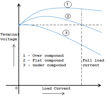
The external characteristics curve of the cumulative compound generator is shown in the figure above. The series excitation benefits the shunt excitation. The degree of the compound is influenced by the rise in series excitation with the increase in load current.
(i) If series winding turns are so adjusted that with the rise in load current, the terminal voltage will increase, which is known as an over-compounded generator. In such a case, because the load current will increase, the series field m.m.f. It will grow and tend to extend the flux and, therefore, the generated voltage. The rise in generated voltage is larger than the IaRa drop so that rather than decreasing, the terminal voltage will increase, as shown by curve 1 in Fig.
(ii) If series winding turns are so adjusted that with the rise in load current, the terminal voltage constantly rests, known as a flat-compounded generator. The series winding of such a machine has fewer ones in the over-compounded device and, therefore, doesn’t increase the maximum amount of flavor load current. Accordingly, the full-load voltage is adequate to the no-load voltage, as shown by curve 2 in Fig.
(iii) If a series field coil has fewer turns than a flat-compound generator, the source voltage falls with an increase in load current, as shown by curve 3 Fig. Such a machine is termed an under-compounded generator.
Internal Characteristic
On the other hand, a generator’s internal characteristics describe the relationship between the generated electromotive force (EMF) and the field current (If) supplied to the field winding. This graph depicts how the EMF generated by the armature varies with changes in the field current while the load current remains constant.
The internal characteristic of a separately excited generator is usually a straight line. This means that the generated EMF is directly proportional to the field current. As the field current increases, the induced EMF also increases linearly. The slope of the internal characteristic represents the generator’s voltage regulation capability. A steeper slope indicates better voltage regulation, while a flatter slope signifies weaker voltage regulation.
Condition for maximum efficiency in DC machine
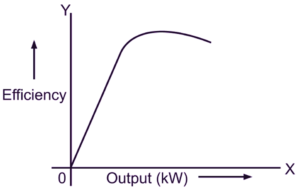
Several conditions must be considered to achieve maximum efficiency in a DC machine. Here are the key factors that contribute to maximizing the efficiency of a DC machine:
Copper Losses
Copper losses occur due to the resistance of the armature and field windings. To achieve maximum efficiency, the copper losses must be minimized. This can be accomplished by using low-resistance copper conductors for the windings and ensuring proper cooling to avoid excessive temperature rise, which increases resistance and, consequently, copper losses.
Iron Losses
Iron losses, also known as core losses, are caused by magnetic hysteresis and eddy currents in the machine’s core. High-quality magnetic materials with low hysteresis and eddy current losses should be used to minimize iron losses. Additionally, optimizing the design of the magnetic circuit, such as using laminated cores to reduce eddy currents, can help reduce iron losses.
Brush and Contact Losses
The meetings, commutator, or slip rings in a DC machine introduce additional brush and contact losses. High-quality brushes with good electrical conductivity and low friction characteristics should be used to minimize these losses. Proper brush alignments and regular maintenance, such as cleaning and lubrication, are also crucial for reducing brush and contact losses.
Windage and Friction Losses
Windage losses occur due to the resistance offered by the machine’s moving parts to the surrounding air. Friction losses are caused by mechanical friction between various components. Minimizing these losses involves using efficient bearings and reducing mechanical friction through proper lubrication. Streamlining the machine’s design and optimizing ventilation can also help reduce windage losses.
Magnetic Saturation
Magnetic saturation occurs when the magnetic field strength reaches its maximum value and can no longer increase proportionally with the increase in current. Operating the machine close to the magnetic saturation point reduces its efficiency. To avoid saturation, the device should be designed to work within its rated current and voltage limits. Additionally, controlling the excitation current to ensure it stays within the optimal range is essential for preventing magnetic saturation.
FAQs
What is a DC compound generator?
A DC compound generator is a type of direct current generator that combines the characteristics of both series-wound and shunt-wound generators. It has two sets of field windings: one connected in series with the armature (series winding) and another connected in parallel (shunt winding). This design allows the generator to maintain a more stable output voltage under varying load conditions.
Key Features:
- Combines series and shunt winding characteristics.
- Provides stable voltage output under varying loads.
- They are used for both light and heavy load conditions.
How does a DC compound generator work?
In a DC compound generator, the series winding carries the entire load current, strengthening the magnetic field as the load increases, helping to boost voltage under heavy loads. The shunt winding maintains a constant magnetic field by carrying a small portion of the current. This combination allows the generator to regulate its output more effectively than pure shunt or series generators, ensuring a steady voltage across different loads.
Working Principle:
- Series winding boosts voltage under heavy loads.
- Shunt winding maintains a stable magnetic field.
- Provides better voltage regulation compared to other DC generators.
What are the types of DC compound generators?
There are two main types of DC compound generators based on how the series and shunt windings are connected:
- Cumulatively Compounded Generator: The series and shunt windings aid each other, meaning the magnetic fields produced by both windings are in the same direction. This results in better voltage regulation as the load increases.
- Differentially Compounded Generator: The series winding opposes the magnetic field of the shunt winding. As the load increases, the voltage decreases due to the opposing effects of the two windings.
Types:
- Cumulative Compound Generator: Series and shunt windings aid each other, providing better voltage regulation.
- Differential Compound Generator: Series winding opposes the shunt winding, causing the voltage to decrease with the load.
What are the advantages of a DC compound generator?
The DC compound generator offers several advantages, such as:
- Improved Voltage Regulation: It maintains a more stable output voltage across varying loads, making it ideal for systems with fluctuating demand.
- Versatility: It handles light and heavy load conditions effectively, making it suitable for various applications.
- Balanced Output: The combination of series and shunt windings allows it to produce a balanced and reliable output, making it useful in sensitive equipment.
Advantages:
- Excellent voltage regulation across loads.
- Versatile, suitable for both light and heavy loads.
- Produces a stable, reliable output.
Where are DC compound generators commonly used?
DC compound generators are widely used in applications that require stable and regulated power output. Some common uses include:
- Power Supply Systems: These are used in power plants and distribution systems where constant voltage is critical.
- Heavy Machinery: Employed in industrial machinery that experiences fluctuating load conditions.
- Electric Traction Systems: Used in trains and trams for reliable and stable voltage supply.
- Lighting Systems: Ideal for maintaining a consistent power supply in large-scale lighting applications.
Applications:
- Power plants and distribution systems.
- Industrial machinery.
- Electric traction (trains, trams).
- Large-scale lighting systems.
