

Polarity Test of Transformer | Purpose, Methods & Importance
When you’re dealing with transformers, understanding their polarity is fundamental. It guarantees the primary and secondary windings are correctly aligned, preventing costly errors and safety hazards. Using a polarity test, you’ll determine if the transformer’s connections are additive or subtractive, essential for efficient energy transfer. Curious about the process and tools involved? The next steps will guide you through conducting this important test confidently and precisely.
Understanding Transformer Polarity
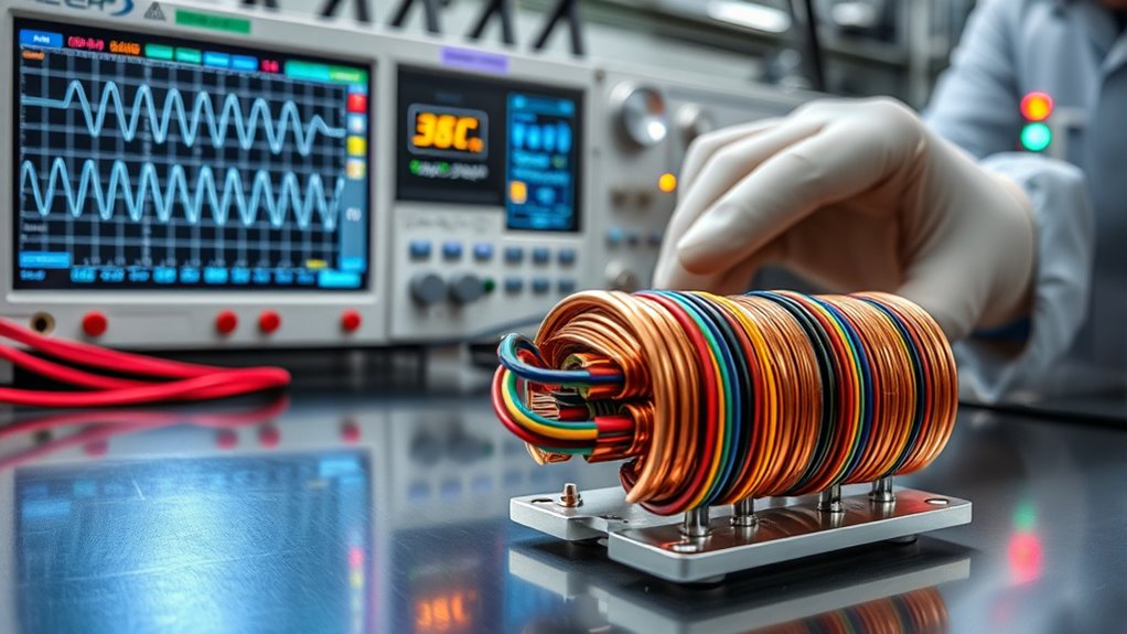
When you explore understanding transformer polarity, you’re focusing on the vital aspect of how voltage and current flow between the primary and secondary windings. Polarity determines whether the voltages are in or out of phase, which can be either additive or subtractive. Additive polarity means the voltages of the windings add up, while subtractive polarity results in the voltages subtracting from each other. The dot convention helps you identify this by marking terminals with dots to show the same instantaneous polarity. Knowing the polarity is essential for preventing phase mismatches, which can cause serious issues like short circuits. By understanding polarity, you guarantee your transformer is compatible with other devices and adheres to industry standards, enhancing operational safety.
Importance of Correct Polarity in Transformers
When dealing with transformers, getting the polarity right is essential for maintaining efficiency and avoiding electrical hazards. Incorrect polarity can cause unnecessary energy losses and pose serious safety risks, especially in systems with high power demands. Understanding and applying the dot convention guarantees that transformers operate safely and reliably, preventing costly failures and disruptions.
Ensuring Transformer Efficiency
Verifying the correct polarity in transformers is vital for maintaining efficiency and preventing unnecessary losses. By conducting a Transformer Polarity Test, you can confirm that polarity is correctly set, guaranteeing efficient energy transfer and avoiding potential voltage mismatches. When transformers are connected in parallel, incorrect polarity can lead to severe issues like short circuits or even damage to equipment. It is important to understand the distinction between additive and subtractive polarity, as it influences how transformers handle load demands, especially in smaller units where voltage stability is essential. Familiarizing yourself with the dot convention helps you identify winding polarities accurately. Proper testing and verification of polarity enhance transformer reliability and promote peak performance across the entire electrical distribution network.
Preventing Electrical Hazards
To prevent electrical hazards, guaranteeing the correct polarity in transformers is essential. The polarity of a transformer plays a critical role in avoiding short circuits and ground faults that can damage equipment and pose safety risks. Incorrect polarity leads to excessive losses, overheating, and fire risks due to improper current flow. Here’s what you should know:
- Correct Polarity: Guarantees efficient operation, reducing energy waste and enhancing system reliability.
- Dot Convention: Helps identify winding polarity for safe parallel connections.
- Compliance: Adhering to industry standards is necessary to prevent liability issues.
- Safety: Proper polarity alignment protects against potential dangers, promoting safe electrical installations.
Identifying Transformer Polarity Using Dot Convention
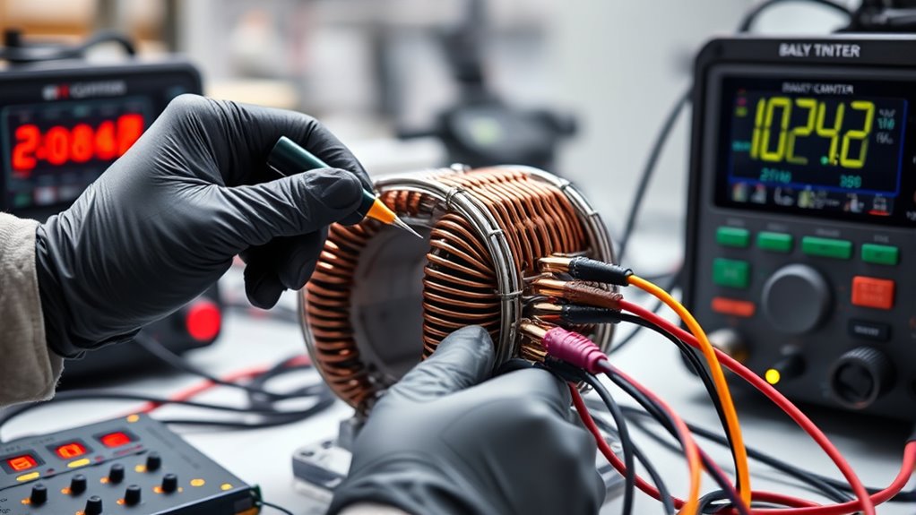
Understanding transformer polarity using the dot convention is essential for anyone involved in electrical installations. The dot convention marks terminals with the same instantaneous polarity, allowing you to determine how current flows between the primary and secondary windings. If the current enters a dotted terminal on the primary, it causes a positive voltage at the secondary’s corresponding dotted terminal, thanks to mutual inductance.
Additive polarity occurs when the secondary’s dotted terminal is diagonally opposite the primary’s. Understanding this helps you avoid common installation errors like short circuits.
Here’s a quick reference table:
| Scenario | Primary Terminal | Secondary Terminal |
|---|---|---|
| Dot Convention | Dotted | Dotted |
| Additive Polarity | Diagonal | Opposite |
| Connection Outcome | Correct Polarity | Avoids Errors |
Use this guide to guarantee safe, efficient connections.
Types of Polarity in Transformers: Additive Vs Subtractive
Building on the foundation of the dot convention, you can further explore the types of polarity in transformers: additive and subtractive. Understanding these is essential for proper operation and avoiding damage. Additive polarity occurs when primary and secondary windings voltages add up, giving a positive reading across secondary terminals. In contrast, subtractive polarity results in a reading showing the difference between these voltages, typically negative.
Here’s how you can identify them:
- Position of X1 Terminal: On the right for additive, on the left for subtractive.
- Voltage Reading: Additive shows positive; subtractive shows negative.
- Transformer Size: Additive is common in smaller transformers, subtractive in larger ones.
- Terminal Arrangement: X terminal diagonal to H terminal in additive setups.
Tools and Equipment Needed for Polarity Testing
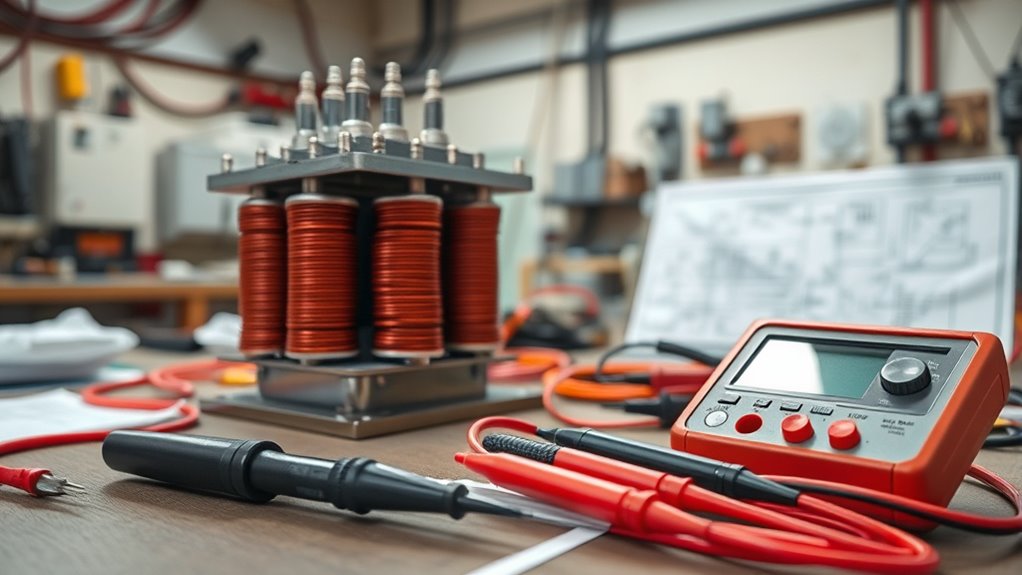
When testing transformer polarity, make sure you have the right tools on hand. You’ll need a low-voltage AC source like a Variac, a digital voltmeter, and secure connecting wires with clips. Don’t forget safety precautions—wear insulated gloves and goggles to protect yourself from electrical hazards.
Essential Testing Instruments
Testing transformer polarity requires a few essential tools to guarantee accuracy and safety. You need the right testing instruments to measure voltage and verify that the test is conducted accurately. Here’s a list to help you get started:
- Low-voltage AC Source: Use a Variac or a low-rated transformer to safely energize the primary winding without exceeding its voltage limits.
- Digital Voltmeter: This is vital for measuring the voltage across the secondary terminals to determine polarity type accurately.
- Connection Wires and Clips: Securely connect the AC source and voltmeter to the transformer’s terminals for reliable electrical contact.
- Circuit Diagram or Recording Table: Document connections and results for clear analysis and comparison of polarity outcomes.
These tools are indispensable for a successful polarity test.
Safety Precautions Required
While conducting a polarity test on transformers, guaranteeing safety is paramount. To minimize hazards, use a low-voltage AC source, like a Variac or battery. This keeps potential dangers from high voltage at bay. Equip yourself with a digital voltmeter, guaranteeing its rating exceeds the maximum expected voltage for precise measurements. Use appropriate connecting wires and alligator clips to securely attach the power source and voltmeter to the transformer terminals, maintaining safe isolation throughout. Always adhere to safety precautions: wear insulated gloves and keep the work area dry and clear of any conductive materials to prevent shocks. Document test connections and results with a circuit diagram or table for clarity and accuracy. Following these steps guarantees a safe testing environment.
Step-by-Step Procedure for Conducting a Polarity Test
Connect a low-voltage AC source to the primary terminals to conduct a polarity test on the transformer. For safety reasons, confirm that the voltage is lower than the transformer’s rated voltage. Here’s a step-by-step guide:
- Connect Primary Winding: Attach a jumper wire from the primary terminal (H1) to the secondary terminal (X1). This helps in accurate voltage measurement.
- Measure Output Voltage: Use a voltmeter to measure the voltage across the secondary terminals while applying power to the primary side.
- Analyze Readings: Check the voltmeter readings. The polarity is additive if the secondary output voltage is the sum of both windings. A lower reading indicates subtractive polarity.
- Confirm Safety: Verify that the voltmeter’s rating exceeds the combined primary and secondary voltages to avoid damage.
ANSI Rules and Guidelines for Transformer Polarity
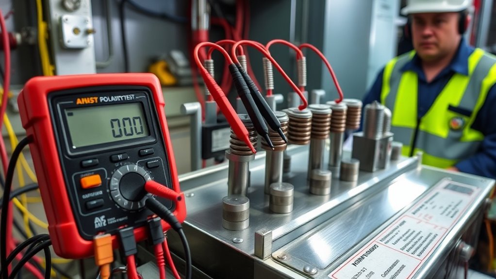
Understanding transformer polarity is essential for guaranteeing the’ accurate and safe operation of electrical systems. The ANSI rules guide you in identifying transformer polarity by focusing on terminal arrangements. The H1 terminal should be on the far left when facing the low-voltage side. The position of the X1 terminal tells you the polarity type: subtractive polarity is indicated when X1 is on the left, directly across from the primary H1 terminal. This impacts how voltages relate during parallel operations. ANSI guidelines stress recognizing these terminal markings and configurations for proper connections. Consistent labeling, per ANSI standards, helps you identify polarity types, making transformer connections safer and more efficient. Always guarantee appropriate adherence to these guidelines.
Common Issues and Adjustments in Polarity Testing
When conducting polarity testing on transformers, it’s crucial to be vigilant about common issues that might arise, particularly with voltmeter connections. Missteps here can lead to incorrect readings and confusion about the polarity type. If you see subtractive polarity when you expect additive, reverse one of the winding connections to adjust. Verify that your voltmeter’s maximum rating surpasses the combined voltage of both primary and secondary windings. Here’s what to focus on:
- Voltmeter Connections: Verify that they’re correct to avoid misleading results.
- Polarity Type Misinterpretation: Reverse winding connections if necessary.
- Turns Ratio Check: Confirm that the ratio aligns with expected values.
- Compare Results: Align your findings with transformer markings and the dot convention for accuracy.
Always double-check to maintain operational integrity.
Ensuring Safety During Polarity Testing
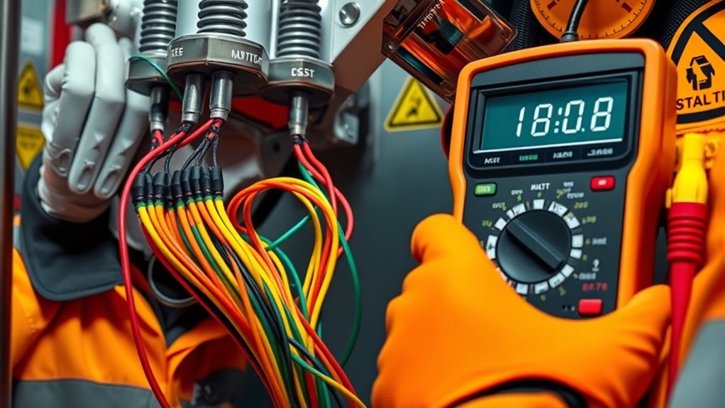
While guaranteeing safety during polarity testing, you should prioritize using the lowest possible AC voltage to minimize hazards. Opt for a Variac or an adjustable AC voltage source to control the voltage precisely. Before you energize the transformer, verify all connections to prevent short circuits or electrical shocks. IConfirmingthat the voltmeter’s maximum voltage rating exceeds the primary and secondary voltages’ sum tis imperative o avoid damage or incorrect readings. Always monitor voltage levels closely and maintain a safe distance from the transformer, adhering to safety guidelines. Don’t forget to wear appropriate personal protective equipment (PPE) to safeguard against potential electrical risks. Following these precautions guarantees a safer testing environment, protecting you and the equipment.
Conclusion
When conducting a polarity test on a transformer, you guarantee its safe and efficient operation by confirming the correct phase relationship between windings. Tools like a low-voltage AC source and a digital voltmeter will determine whether the transformer has additive or subtractive polarity. This critical step helps you prevent installation errors, energy losses, and safety risks. Stay compliant with ANSI standards and prioritize safety to maintain the reliability of your electrical systems.
FAQs
1. How to Perform a Polarity Test?
To perform a polarity test, connect your transformer connections correctly. Use testing equipment like a low-voltage AC source and a voltmeter. Secure connections and check voltmeter readings for polarity, ensuring you’re following safety precautions throughout the process.
2. What Is the Polarity Rule of a Transformer?
You need to understand the polarity rule for transformer connections. It guarantees correct electrical phase alignment. When the current enters the primary’s dotted terminal, the secondary’s dotted terminal should be positive, preventing phase mismatches and ensuring safe operation.
3. How to Identify the Positive and Negative Terminals of a Transformer?
You can identify transformer terminals by checking terminal markings for ‘H’ and ‘X’ labels. Use the dot convention for identification. If markings are unclear, perform a polarity test with a voltmeter to confirm.
4. How Do You Determine the Polarity of a Current Transformer?
To determine a current transformer’s polarity identification, apply a low AC voltage to the primary and check the secondary voltage using a voltmeter. A positive reading indicates additive polarity, while a negative one suggests subtractive polarity.
