

Equivalent Circuit of Induction Motor – Working & Analysis
When you consider the equivalent circuit of an induction motor, you’re stepping into a world where electrical intricacies meet mechanical prowess. This circuit is more than just a diagram; it’s a blueprint for understanding how stator and rotor components interact and influence motor performance. You can uncover insights into efficiency and torque by examining key elements like rotor impedance and stator resistance. But what’s the real impact of slip on these dynamics? And how does this knowledge translate to practical applications? There’s much more to uncover about how this circuit shapes motor reliability and efficiency.
Understanding Induction Motors
Induction motors are fascinating machines that rely on electromagnetic induction to function. As you explore how these motors work, you’ll encounter the central components: the stator and rotor. The stator generates a rotating magnetic field, which induces current in the rotor. This induced current is crucial as it creates torque, driving the motor’s operation.
Understanding the slip is essential when studying induction motors. Slip is the difference between the motor’s synchronous and rotor speeds, usually ranging from 0% to 5-10% under full load. This slip allows the rotor to generate enough torque to handle varying loads efficiently.
The equivalent circuit of an induction motor is a helpful tool in understanding motor performance. It simplifies the complex interactions between the stator’s resistance, reactance, and the rotor’s characteristics. By transforming the rotor impedance and current to the stator side, you can analyze the motor’s behavior similarly to a two-winding transformer.
Frequency also plays a vital role in motor operation. It affects the stator’s magnetic field and, consequently, the rotor’s induced current.
Mastering these concepts will deepen your appreciation of how induction motors balance efficiency and performance.
Equivalent Circuit Basics
Understanding the basics of an equivalent circuit is crucial when analyzing induction motor performance. An equivalent circuit reflects the motor’s electrical and magnetic characteristics, offering insight into its behavior under various conditions.
At its core, the equivalent circuit consists of a stator circuit with resistance (R1) and reactance (X1), representing the stationary part of the motor. On the rotor side, resistance is modeled as (R2/s), where ‘s’ is the slip, and reactance is denoted by (X2). These elements are vital for understanding how the motor interacts with electrical power.
In addition to these components, magnetizing reactance (XM) plays a significant role, accounting for the motor’s ability to convert electrical energy into magnetic energy. By analyzing the equivalent circuit, you can derive key performance characteristics like input power, rotor input power, and developed power.
These metrics help you evaluate the motor’s power factor and overall efficiency. At the same time, an exact equivalent circuit includes additional components for detailed analysis, and an approximate equivalent circuit simplifies calculations, particularly for larger motors where voltage drops are minimal.
Understanding these basics equips you to effectively assess an induction motor’s performance and efficiency.
Exact Equivalent Circuit
In motor analysis, delving into the exact equivalent circuit of an induction motor provides a comprehensive understanding of its intricate dynamics. This circuit captures all the essential parameters that affect motor performance, including core loss, copper losses, and rotor power.
- Stator Winding Resistance and Inductance: The exact equivalent circuit includes the stator winding resistance (R1) and inductance (X1). These elements account for copper losses and the reactance in the stator, which is crucial for evaluating efficiency and performance.
- Core Loss Component: The circuit incorporates a core loss component (Rc) to represent energy losses due to hysteresis and eddy currents in the magnetic core. This ensures that the analysis considers all energy losses accurately.
- Rotor Resistance and Slip: Rotor power is depicted as R/s, where R is the rotor resistance and s is the slip. This part of the circuit allows you to calculate the useful power output using the formula (1 – s) / s, providing insights into performance under various conditions.
The exact equivalent circuit models the rotor winding resistance and inductance as referred to the stator side, offering a precise portrayal of the rotor’s interaction with the stator’s magnetic field.
Approximate Equivalent Circuit
For those delving into motor analysis, the approximate equivalent circuit offers a streamlined approach to understanding an induction motor’s performance. By relocating the shunt branches to the input terminals, this model simplifies the examination of motor behavior while maintaining a constant voltage across these branches.
It’s particularly useful for large induction motors, helping you focus on essential performance calculations without getting bogged down by complexity.
In this model, the resistance varies with slip, which directly influences the motor’s developed mechanical power. While resistance changes, other factors like reactance remain constant, making the model easier to manage.
The impedance in the approximate equivalent circuit is expressed as ( Z_{AB} = (R_s + frac{R_r}{s}) + j(X_s + X_r) ), providing a clear path for calculating and assessing motor performance under different conditions.
This circuit configuration allows you to account for slip effects on resistance, giving you a practical tool to evaluate motor efficiency and behavior. Engineers rely on this model as a standard for performance calculations, ensuring they can accurately predict how an induction motor will operate across varying operational scenarios.
Stator Circuit Components
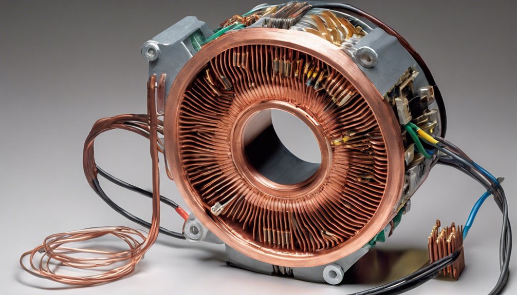
When you examine the stator circuit components of an induction motor, you’ll notice that phase winding resistance (R) and magnetizing reactance (X) play pivotal roles.
The winding resistance accounts for the losses during operation, while the magnetizing reactance is crucial because it generates the magnetic field needed for rotor movement.
Understanding these elements helps you analyze the motor’s performance under various conditions.
Stator Winding Resistance
An induction motor’s efficiency is significantly influenced by its stator winding resistance, a crucial factor in determining copper losses as current flows through the windings. In three-phase induction motors, the stator resistance plays a vital role in the equivalent circuit model. Here’s how:
- Balanced Performance: The total stator resistance is the sum of each phase’s resistance, and for optimal balanced performance, these values should be equal. This symmetry ensures that each phase handles the current uniformly, reducing inefficiencies.
- Operational Thermal Conditions: As temperature rises, so does the stator resistance, affecting the motor’s performance. This increase in resistance leads to higher copper losses, so you need to adjust calculations for operational thermal conditions to maintain efficiency.
- Magnetizing Current Impact: The no-load current splits into magnetizing and core-loss current. The stator winding resistance affects the total current drawn, influencing voltage drop and motor performance under varying loads.
Understanding and managing the stator winding resistance is essential for optimizing motor performance. By closely monitoring these factors, you can ensure your motor operates efficiently, minimize losses, and maintain a reliable equivalent circuit model.
Magnetizing Reactance Importance
After grasping the role of stator winding resistance in your motor’s performance, it’s time to explore another key component: magnetizing reactance. This component establishes the magnetic field necessary for torque generation, often dominating the stator impedance.
Unlike transformers, induction motors need a higher magnetizing current—about 25-40% of the rated current—due to the air gap’s higher reluctance. This means that most of the current is dedicated to magnetization rather than actual power consumption at no-load conditions.
Accurate modeling of magnetizing reactance is vital for predicting motor performance. It directly impacts the voltage drop across the motor, affecting efficiency and reliability under varying load conditions. You might experience unexpected energy losses that could compromise overall efficiency if underestimated.
By understanding magnetizing reactance, you can develop effective control strategies to enhance performance and minimize energy losses.
The magnetizing reactance is pivotal in your induction motor’s operation. Proper management ensures that your motor runs efficiently, with minimized energy wastage and optimized torque generation, making it an indispensable element in modern motor design and application.
Rotor Circuit Components
When examining the rotor circuit components of an induction motor, focus on calculating rotor impedance. This combines resistance and variable reactance affected by slip frequency.
You’ll see that as slip frequency changes, it directly influences the induced voltage dynamics in the rotor windings, crucial for motor performance.
Understanding these aspects helps you evaluate how rotor impedance impacts torque and efficiency under different load conditions.
Rotor Impedance Calculation
Understanding the rotor impedance is crucial for analyzing the performance of an induction motor. The rotor impedance is represented as ( Z_r = R_r + jX_r ), where ( R_r ) is the rotor resistance and ( X_r ) is the rotor reactance. Here’s what you need to know:
- Rotor Resistance: This component ( R_r ) stays constant during operation. It’s a key part of the rotor impedance and directly affects the current flow through the rotor circuit.
- Rotor Reactance: Unlike resistance, rotor reactance ( X_r ) varies with slip frequency and rotor inductance. You calculate it using ( X_r = 2pi f_r L_r ), where ( f_r ) is the slip frequency and ( L_r ) is the rotor inductance. This variability is essential for understanding how the rotor adapts to different operating conditions.
- Impact on Performance: The rotor current ( I_r ) is inversely proportional to the rotor impedance, directly influencing the motor’s torque output and efficiency. Additionally, the rotor voltage ( E_r = sE_s ), with ( s ) as slip and ( E_s ) as stator voltage, demonstrates how rotor parameters transform to the stator side, affecting air-gap power and torque.
Accurate calculations of these elements are vital for effectively evaluating your motor’s performance.
Slip Frequency Effects
Building on the concept of rotor impedance, it’s important to explore how slip frequency affects the rotor circuit components of an induction motor. Slip frequency is crucial as it determines the frequency of the induced voltage in the rotor. Calculated by multiplying the slip (s) with the stator supply frequency (f), it directly impacts the induced rotor current. As the rotor speed nears synchronous speed, the slip frequency decreases, reducing the induced rotor current.
This relationship is vital because the induced rotor current, given by the formula I_r = E_r / Z_r, where E_r is the rotor-induced voltage, is fundamental in determining the motor’s performance.
Rotor impedance, comprising resistance and reactance, varies with slip frequency. As slip decreases, rotor reactance increases, impacting the induction motor’s torque characteristics. The motor’s ability to produce optimal torque generally occurs within a specific slip range.
Therefore, understanding slip frequency is essential for analyzing and optimizing rotor performance. Proper slip frequency management ensures that the induction motor operates efficiently and effectively, maintaining the desired torque characteristics and performance levels.
Induced Voltage Dynamics
A crucial aspect of induction motor performance lies in the dynamics of induced voltage within the rotor circuit. This induced voltage arises from the interaction between the rotor windings and the stator’s rotating magnetic field. The slip frequency, the difference between synchronous and rotor speeds, directly influences this process.
Let’s dive into the key components:
- Rotor Impedance: It consists of resistance and reactance. While the resistance (R_r) remains constant, the reactance (X_r) varies with rotor inductance and slip frequency. This variation affects the motor’s overall performance and efficiency.
- Rotor Current: Generated by the slip-frequency voltage (sE), where ‘s’ stands for slip. The rotor current interacts with the magnetic field, which is crucial in torque production. The equivalent circuit uses phasor form to depict the rotor current, showing its relationship with rotor impedance.
- Torque Production: The rotor current and magnetic field interaction produces torque. As slip frequency changes, so do the efficiency and torque output of the motor, making understanding these dynamics essential for optimizing motor performance.
Understanding these dynamics helps you optimize motor efficiency and performance effectively.
Power Relations and Calculations
When analyzing the power relations and calculations in an induction motor, it’s crucial to consider how energy flows through the system. The input power to the stator is a key factor, calculated as ( P_{text{input}} = 3V_s I_s cos varphi_s ), where ( V_s ) is the stator voltage, ( I_s ) the stator current, and ( varphi_s ) the phase angle. This input power is partly converted to air-gap power ( P_g ), which can be expressed as ( P_g = V_s I_r cos varphi_r ) or in terms of rotor impedance and slip ( s ).
The developed power in the rotor is crucial for the motor’s output, given by ( P_{text{developed}} = (1 – s) P_g ). Pay attention to rotor copper loss ( P_{text{copper}} = s cdot P_g ), which increases with slip, affecting efficiency. Efficiency is defined by the ratio of useful power output to input power, emphasizing optimizing these power relations.
| Parameter | Formula |
|---|---|
| Input Power | ( 3V_s I_s cos varphi_s ) |
| Air-Gap Power | ( V_s I_r cos varphi_r ) |
| Developed Power | ( (1 – s) P_g ) |
| Rotor Copper Loss | ( s dot P_g ) |
Understanding these relationships ensures optimal motor performance and efficiency.
Single Phase Induction Motors
Understanding power relations in induction motors provides a foundation for exploring single-phase motors. These motors operate on the rotating magnetic field principle, achieved through a single-phase AC supply. The field is resolved into two imaginary rotating fields to generate torque.
An auxiliary winding is employed to start these motors. This winding, often configured through split-phase or shaded-pole methods, creates a necessary phase shift.
- Starting Torque: The starting torque in a single-phase induction motor is relatively low, typically about 1.5 to 2 times the full-load torque. This makes it ideal for smaller loads like fans and household devices.
- Equivalent Circuit: When analyzing single-phase induction motors, the equivalent circuit often simplifies by neglecting core loss and focusing on the resistive and inductive reactance of the stator windings. This approach aids in understanding the dynamics of rotor circuits.
- Slip: These motors can maintain operation under varying conditions, with slip reaching up to 2. While efficient under certain loads, they’re generally less efficient than three-phase motors.
Torque and Performance Analysis
To analyze the torque and performance of induction motors effectively, you need to understand the relationship between slip and torque production. Slip is the difference between synchronous speed and rotor speed divided by synchronous speed. It’s crucial because as slip increases, so does rotor current, enhancing magnetic field interaction and torque.
Torque can be calculated using the equation ( T = frac{P_g}{omega_s} ), where ( P_g ) is the air-gap power and ( omega_s ) is the synchronous speed.
The equivalent circuit model offers a detailed way to calculate torque by examining rotor impedance, comprising rotor resistance and reactance. These components impact overall motor performance and help you determine how efficiently an induction motor operates. Typically, full-load efficiency ranges from 85% to 97%, influenced by slip, rotor speed, and input power.
Torque-speed characteristics reveal key performance metrics, such as breakdown torque (175% to 300% of rated torque) and locked-rotor torque (75% to 275% of rated torque).
These metrics give you insights into how the motor will perform under different loads and conditions, enabling better design and operational decisions.
Applications and Practical Insights
Analyzing the torque and performance of induction motors equips you with insights into their practical applications. The equivalent circuit is key to understanding how these motors operate under different loading conditions. It simplifies analysis, allowing you to predict efficiency and operational behavior precisely.
Here’s how you can leverage this knowledge:
- Variable-Frequency Drives (VFDs): By utilizing the equivalent circuit, you can independently design and implement VFDs that control motor speed and torque. This leads to enhanced energy efficiency and optimized performance in various applications.
- Troubleshooting: The equivalent circuit is an invaluable tool in diagnosing motor issues. It helps you pinpoint potential losses due to copper, iron, and mechanical factors, which can affect overall efficiency and performance.
- Motor Protection and Control Systems: Understanding the equivalent circuit aids in developing motor protection and control systems. This includes creating starters and voltage stabilizers, ensuring reliable operation, and safeguarding against faults.
Conclusion
You’ve now clearly understood how the equivalent circuit of an induction motor helps analyze and optimize motor performance. You can assess and enhance efficiency by focusing on components like stator and rotor impedances. Keep in mind how slip affects torque generation, ensuring motors operate reliably. Whether dealing with single-phase motors or complex systems, these insights are crucial for practical applications, making you better equipped to handle various loading conditions and improve operational outcomes.
FAQs
1. What Is the Equivalent Circuit of an Induction Motor?
You’re exploring an essential tool for analyzing motor performance. It models electrical parameters like resistances and reactances, helping you understand how the motor operates under different loads. This circuit’s insights optimize efficiency and enhance operational understanding.
2. Why Do We Draw the Equivalent Circuit of Single Phase Induction Motor?
You draw the equivalent circuit of a single-phase induction motor to simplify analysis, calculate key parameters, and predict performance. It helps you understand internal losses, slip, and torque, ensuring efficient design, operation, and control strategies.
3. What Are the Equivalent Circuit Parameters of 1 Phase Induction Motor?
You need to identify key parameters like stator resistance (R1), leakage reactance (X1), magnetizing reactance (Xm), core loss resistance (Rc), rotor resistance (R2/s), and rotor reactance (X2) for a single-phase induction motor’s equivalent circuit.
4. How Would You Determine the Equivalent Circuit Parameters of a Three-Phase Induction Machine?
You’d determine the parameters by performing a no-load test for magnetizing reactance and core losses. Conduct a blocked rotor test to find stator and rotor resistances and reactances. Use transformation ratios to refer rotor values to the stator.
