

Half Wave Rectifier Circuits: Working, Applications, and Benefits
When you explore the world of electronics, the half-wave rectifier circuit is a fundamental concept you can’t ignore. It uses a single diode to transform AC into pulsating DC, but have you considered why it only allows positive half-cycles? While it’s efficient for simple tasks, the circuit’s ripple factor and efficiency might surprise you. These characteristics make it suitable for specific applications yet hint at its limitations. What if there’s more to this seemingly straightforward circuit, such as unique benefits or hidden drawbacks? Let’s investigate what truly sets it apart.
Key Takeaways
- A half-wave rectifier uses a single diode to convert AC to pulsating DC by allowing only positive half-cycles.
- The circuit consists of a diode, transformer, and resistive load for voltage adjustment and rectification.
- The average DC output voltage is about 31.8% of the peak AC voltage.
- Efficiency is approximately 40.5%, making it suitable for low-power applications.
- Smoothing capacitors can reduce ripple voltage but don’t match full-wave rectifier performance.
Basics of Half-Wave Rectification
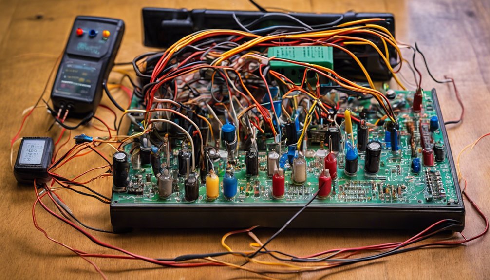
A single diode is all you need to grasp the basics of half-wave rectification. In a half-wave rectifier, this diode allows only the positive half-cycle of an AC signal to pass through, transforming AC to pulsating DC. This process is simple yet effective, especially for low-power applications.
By blocking the negative half-cycle, the diode guarantees the output voltage is a series of pulses, averaging about 31.8% of the peak AC voltage. This results in a lower DC voltage, which mightn’t suit high-power needs but is ideal for tasks like AM radio detectors or simple battery chargers.
The efficiency of a half-wave rectifier stands at approximately 40.5%. This means that a significant portion of input power is wasted, indicating that while it’s not the most efficient, it remains useful for its simplicity and low-cost design.
The ripple factor is around 1.21, meaning there is a considerable amount of ripple in the output. This can affect connected devices, so it’s critical to consider it when designing circuits.
Adding a load resistor can help manage the pulsating DC but will not eliminate the ripple. Understanding these nuances is key to using them effectively in specific applications.
Circuit Components and Operation
In a half-wave rectifier circuit, the primary components include a diode, a transformer (if voltage adjustment is necessary), and a resistive load.
You’ll find that the diode plays a critical role by allowing only the positive half-cycle of the AC waveform to pass. The diode is forward-biased during this period, resulting in a pulsating DC output. It blocks the negative half-cycle, so you’ll get zero output voltage at that time.
A transformer is handy for adjusting the voltage, stepping the AC voltage up or down before it hits the diode.
Meanwhile, the average DC output voltage is roughly 0.318 times the peak input voltage or 0.45 times the RMS voltage. A half-wave rectifier’s efficiency is relatively low, capping at about 40.5%, since it uses only half of the input AC waveform.
Adding smoothing capacitors across the load might enhance the output’s stability. These components help reduce ripple voltage, but their effectiveness depends on the load resistance.
Understanding these components and their operation is essential for optimizing a half-wave rectifier circuit that fits your needs.
Output Characteristics and Waveform
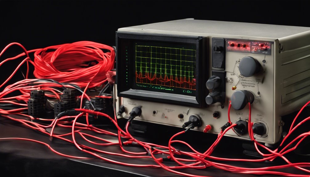
The pulsating heartbeat of a half-wave rectifier is its output waveform, transforming AC into a series of positive voltage peaks. This transformation allows only the positive half-cycles of the input AC signal to pass, creating a pulsating DC signal. During the negative half-cycles, the output drops to zero, resulting in a distinct pattern of voltage peaks separated by zero voltage periods.
Your half-wave rectifier’s average DC output voltage is about 31.8% of the peak voltage (Vmax), calculated using Vdc = 0.318 * Vmax. The ripple frequency of this output waveform matches the input AC frequency, meaning any fluctuations in your AC input directly affect the DC output’s stability.
Expect considerable voltage fluctuations in the output with a ripple factor of around 1.21. To improve this, consider using smoothing capacitors across the load resistor. These capacitors help reduce the ripple, lending more stability to the pulsating DC output.
However, the effectiveness of this smoothing largely depends on the capacitor’s size and discharge rate. Therefore, while smoothing capacitors can enhance the output, they can’t eliminate the inherent ripple of a half-wave rectifier.
Efficiency and Performance Metrics
While a half-wave rectifier’s output characteristics highlight its ability to transform AC into a pulsating DC signal, understanding its efficiency and performance metrics provides a deeper insight into its operational limitations.
The efficiency of a half-wave rectifier, calculated as the ratio of DC output power to AC input power, maxes out at about 40.5%. This modest figure underscores its limitations in power conversion compared to other rectifiers.
One key performance metric is the ripple factor, which for a half-wave rectifier is approximately 1.21. This high ripple factor indicates significant voltage fluctuation, making the DC output less stable and desirable for smooth power applications.
The Peak Inverse Voltage (PIV) is also essential; this metric tells you the maximum reverse voltage the diode can handle without breaking down, ensuring the rectifier operates reliably.
Here are some factors to keep in mind:
- Efficiency: Maxes out at 40.5%, limiting power conversion.
- Ripple Factor: High at 1.21, leading to voltage fluctuation.
- Transformer Utilization Factor: Lower compared to full-wave, reducing effective power supply.
These factors highlight the half-wave rectifier’s role as an introductory solution in simple power conversion tasks.
Practical Applications and Comparisons
Half-wave rectifiers are frequently used in low-power applications like AM radio detectors and simple battery chargers. This is largely due to their cost-effectiveness and simplicity.
A half-wave rectifier converts AC input into DC output voltage, allowing only half of the AC cycle to pass through. This inherently limits its efficiency to about 40.5%, making it unsuitable for power supplies where high efficiency is vital.
The ripple factor for a half-wave rectifier is around 1.21, indicating a significant ripple level in the DC output voltage. This translates to less stability than full-wave rectifiers offer.
Full-wave rectifiers, which utilize both halves of the AC cycle, provide a smoother and more stable output by reducing the ripple factor.
Half-wave rectifiers are often paired with smoothing capacitors to mitigate the ripple effect. While this helps stabilize the output voltage somewhat, it doesn’t match the performance of full-wave rectifiers in applications requiring a steady DC supply.
Fundamentally, if you’re considering practical applications, understanding the trade-offs between the simplicity of a half-wave rectifier and the efficiency of full-wave rectifiers is key.
Conclusion
You’ve discovered the half-wave rectifier circuit’s simplicity and utility in converting AC to pulsating DC. Despite its ease of use, it is crucial to recognize its limitations, such as low efficiency and high ripple factor. These constraints make it suitable for low-power tasks but not for high-efficiency needs. Understanding its characteristics lets you decide when to use this circuit over more complex alternatives like full-wave rectifiers.
FAQs
1. What Are the Disadvantages of a Half Wave Rectifier?
You’re dealing with efficiency issues, voltage ripple, and limited output. Transformer utilization suffers, affecting load current. Diode selection impacts heat generation and signal distortion. Frequency response and circuit complexity further complicate matters, making it less ideal for stable applications.
2. How Do You Connect a Half Wave Rectifier Circuit?
To connect a rectifier, use a transformer to step down the voltage, connect a diode for rectification, and add a load resistor. Ensure the diode’s characteristics match your needs. Analyze efficiency, understand waveform shapes, consider safety, and troubleshoot carefully.
3. Are Half Wave Rectifiers Used as a Mosquito Repellent?
You might the half-weave rectifiers repel mosquitoes, but they’re not designed for that. They focus on electrical circuits, not insect control. Their efficiency in waveform analysis doesn’t impact mosquito behavior or electromagnetic fields related to most Quito-repellent devices.
4. What Is a Full Wave Rectifier Circuit?
You’re curious about full wave rectifiers. They efficiently convert AC to DC using a diode bridge or a transformer, reducing ripple voltage for better output waveform. They’re ideal for applications needing precise voltage regulation in circuit design.
