

Torque-Slip Characteristics of Induction Motors Explained
When you examine the torque-slip characteristics of an induction motor, you’ll find that understanding this relationship is key to optimizing its performance. You can see how different operational conditions impact motor behavior by analyzing the torque-slip curve, divided into low, medium, and high slip regions. Adjusting rotor resistance can shift the maximum torque point and reshape the curve, enhancing efficiency. Are you curious about how this plays out in single-phase and three-phase motors and what practical applications this knowledge reveals? Let’s explore how these characteristics influence real-world motor operation and efficiency.
Key Takeaways
- The torque-slip curve shows the relationship between torque and slip in an induction motor.
- Maximum torque (pull-out torque) occurs in the medium slip region where rotor resistance equals slip reactance.
- High slip beyond maximum torque causes torque reduction, potentially leading to motor stoppage under heavy load.
- Adjusting rotor resistance shifts the maximum torque slip value, improving motor performance under varying loads.
- Understanding torque-slip characteristics is crucial for optimizing motor performance and efficiency in diverse applications.
Understanding Torque-Slip Characteristics
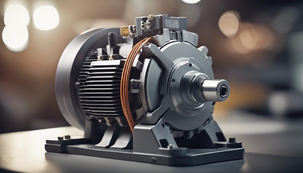
Understanding the torque-slip characteristics of an induction motor is important for analyzing how the engine performs under various load conditions. The relationship between torque and slip is represented by a torque-slip curve, which resembles a rectangular hyperbola. This curve is divided into three regions: low, medium, and high slip, each affecting motor performance differently.
The motor reaches its maximum pull-out torque in the medium slip region, where rotor resistance equals slip times the reactance (R = sX). This pull-out torque indicates the motor’s capability to handle short-term overloads efficiently.
As you move into the high slip region, the torque decreases beyond the maximum torque point. Eventually, the motor slows down and stops if the load becomes too high.
Rotor resistance significantly impacts the torque-slip characteristics. By optimizing rotor resistance, you can enhance the motor’s performance and efficiency. At synchronous speed (zero slip), the torque is minimal, and as the slip increases, the torque rises until it peaks at the pull-out torque.
Understanding this curve is essential for ensuring your induction motor operates efficiently under varying load conditions, maximizing reliability and performance.
Single-Phase Induction Motor Analysis
When analyzing single-phase induction motors, you’ll notice the importance of starting torque behavior to overcome the initial canceling torques.
Efficiency and power factors also play critical roles, affecting overall performance and energy consumption.
Understanding these factors helps you optimize motor operation and guarantee reliable performance.
Starting Torque Behavior
Single-phase induction motors need external starting torque to overcome their initial inertia and begin rotation. This external starting torque is vital because the motor’s natural torque difference between the forward and backward fields determines its starting direction.
You get forward rotation when the forward field produces greater torque than the backward field. Conversely, the motor will start in the backward rotation if the backward field generates more torque.
Understanding starting torque behavior is essential for analyzing the performance of a single-phase induction motor. The torque difference between the forward and backward fields ultimately dictates the motor’s starting direction, greatly impacting motor performance.
Without sufficient external starting torque, the motor can’t overcome its initial inertia, leading to inefficient operation or failure to start altogether.
In practical terms, ensuring that your motor receives adequate external starting torque is key to reliable operation. The motor must overcome initial inertia to achieve the desired rotation and performance.
Efficiency and Power Factor
Analyzing the efficiency and power factor of single-phase induction motors reveals key insights into their performance and potential areas for improvement. Single-phase motors typically have an efficiency range of 40% to 50%. This relatively low efficiency is primarily due to asymmetric magnetic fields inherent in their design. These fields cause energy losses, which reduce overall motor performance.
To address these issues, capacitors are often used in single-phase motors. They play an important role in power factor correction, which helps reduce energy losses and improve motor efficiency. The power factor of single-phase motors can vary between 0.6 and 0.9, and enhancing this metric is crucial for better motor performance.
Power factor correction involves using capacitors to balance the inductive and capacitive reactance in the motor’s electrical circuit. This correction minimizes the phase difference between voltage and current, thereby improving the power factor. Doing so can notably reduce energy losses and enhance the motor’s efficiency.
Understanding an induction motor’s torque slip characteristics further aids in optimizing its performance. By focusing on efficiency and power factor, you can ensure that single-phase induction motors operate more effectively, providing better overall performance and reliability.
Three-Phase Induction Motor Analysis
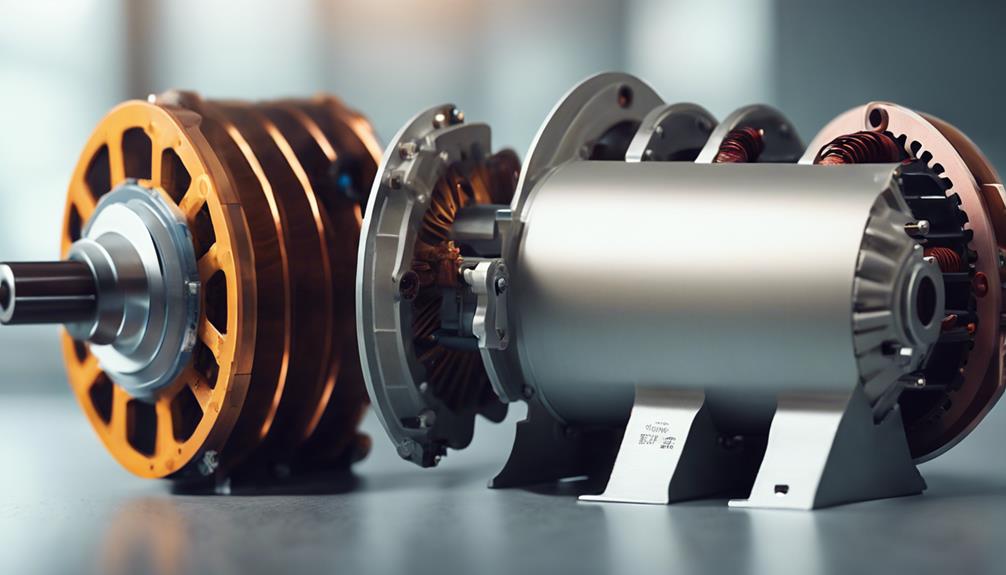
To understand three-phase induction motor analysis, you must grasp how torque-slip characteristics influence the motor’s performance across different operating modes. The torque-slip curve is essential for examining motoring, generating, and braking.
In the motoring mode, the motor operates below synchronous speed, where torque is proportional to slip. The torque-speed characteristics in this mode show how the engine delivers its mechanical output efficiently. The motoring mode is fundamental for most industrial applications. As you increase the slip, the torque increases until it hits the pull-out torque, beyond which the motor can’t handle the load.
Conversely, in the generating mode, the motor runs above synchronous speed. Here, the motor receives mechanical energy and converts it into electrical energy, effectively working as a generator.
In the braking mode, reversing the supply voltage polarity quickly stops the motor using the plugging method. This mode is essential for safety and control.
Understanding these low, medium, and high slip regions is crucial for optimizing the motor’s performance. The full-load torque and electromagnetic induction principles play significant roles in these analyses, ensuring the motor operates efficiently across various conditions.
Rotor Resistance Impact
Building on understanding torque-slip characteristics, let’s explore how rotor resistance impacts the motor’s performance and efficiency. When you add resistance to the rotor circuit, it doesn’t change the maximum torque value. Instead, it affects the slip value at which maximum torque occurs, shifting it to a higher slip. This alteration in the torque slip curve can greatly impact motor performance.
Key impacts of rotor resistance:
- Slip Value Adjustment: The slip value at which maximum torque occurs increases, allowing the motor to handle higher loads without stalling.
- Torque Slip Curve Shape: The torque slip curve becomes wider, making the motor more flexible under varying loads.
- Breakdown Torque: The breakdown torque remains unaffected by changes in rotor resistance.
- Motor Performance Optimization: By adjusting rotor resistance, you can optimize motor performance for specific applications, balancing efficiency and load handling.
- Rotor Circuit Impact: The rotor circuit resistance changes can influence the motor’s overall efficiency and operational stability.
Understanding these impacts is essential for fine-tuning motor performance to meet specific requirements. By managing rotor resistance effectively, you can ensure the motor operates efficiently across various load conditions, enhancing performance and longevity.
Advantages and Disadvantages
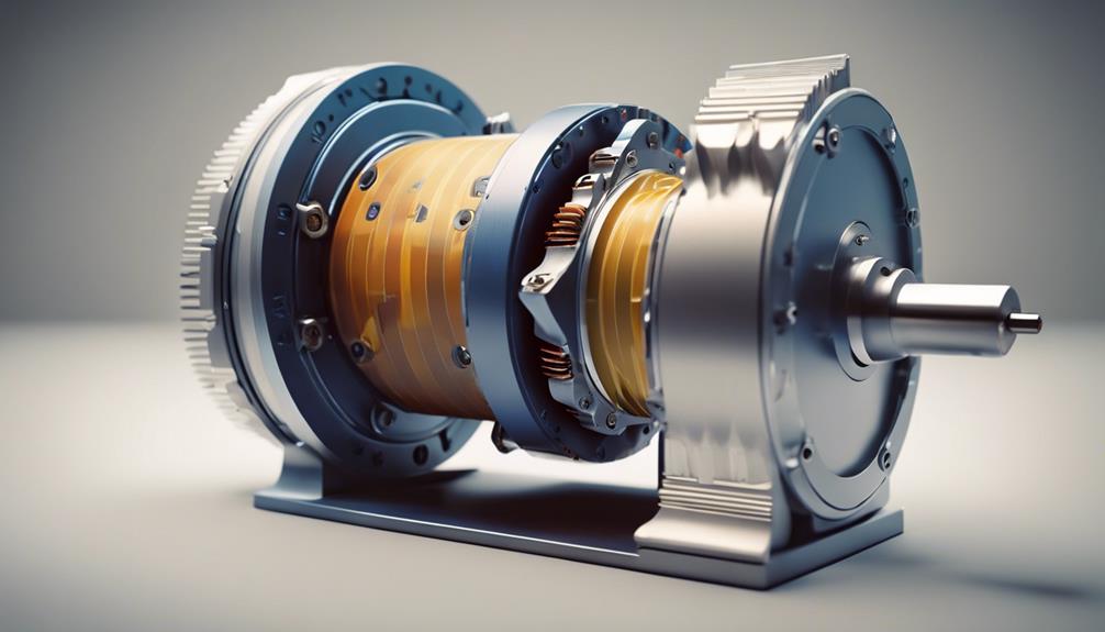
Understanding the advantages and disadvantages of torque-slip characteristics helps you optimize motor performance effectively. One key advantage is that you can enhance motor performance and efficiency across various applications by analyzing slip characteristics.
Three-phase motors, in particular, offer better performance in constant torque applications than single-phase motors. This makes them ideal for industries requiring reliable and steady operation, such as HVAC, mining, and wind turbines.
However, there are some downsides to take into account. The limited speed control capabilities of three-phase motors can be a drawback, especially when precise adjustments are necessary. At low slip values, energy wastage becomes a concern, reducing overall efficiency. Recognizing these drawbacks allows you to make informed motor use and maintenance decisions.
Another benefit is the ability to understand motor behavior under different load conditions. By knowing how slip characteristics affect maximum torque, you can better match the motor to specific tasks and conditions, improving performance and efficiency. This knowledge is essential for applications where varying load conditions are common, such as electric vehicles.
Practical Applications
Analyzing torque-slip characteristics has extensive practical applications across various industries, enhancing motor performance and efficiency. By understanding the torque-slip characteristics curve, you can optimize the operation of both Three-Phase and Single-Phase induction motors. This knowledge is essential for designing efficient electric vehicle motors, achieving maximum torque, and improving motor efficiency.
Consider these practical applications:
- Electric Vehicles: Designing motors with essential performance and maximum torque to enhance driving efficiency.
- Wind Turbines: Improving the energy efficiency of generators by analyzing the slip characteristics of Three-phase motors.
- HVAC Systems: Ensuring reliable motor operation under varying load conditions by leveraging the slip characteristics of single-phase motors.
- Mining Equipment: Determining motor capabilities for heavy-duty applications through torque-slip analysis.
- Household Appliances: Enhancing motor control and longevity in electric motor controllers by understanding the motor’s torque-slip dynamics.
Conclusion
Understanding the torque-slip characteristics of induction motors, you’ve seen how analyzing single-phase and three-phase versions and optimizing rotor resistance can greatly enhance performance.
While each motor type has advantages and disadvantages, recognizing these traits allows you to customize motor operations for specific applications.
BDoingso guarantees your motor runs efficiently and reliably, meeting the demands of various tasks with peak performance.
FAQs
What is the torque-slip characteristic of an induction motor?
The torque-slip characteristic of an induction motor shows the relationship between the motor’s torque and its slip. Slip is the difference between the motor’s synchronous speed and actual rotor speed, expressed as a percentage. The torque produced by the motor varies with slip, which helps understand motor performance under different loads.
Key Terms:
- Torque: Rotational force produced by the motor.
- Slip: The difference between synchronous speed and rotor speed.
How does slip affect the torque in an induction motor?
In an induction motor, torque production depends on the slip, and this relationship can be divided into three regions:
- Low Slip (No Load): At low slip values, close to synchronous speed, the motor produces low torque because the relative motion between the stator’s rotating magnetic field and the rotor is minimal.
- Moderate Slip (Max Torque): As the slip increases with load, torque increases until it reaches a maximum value at a certain slip. This is called the pull-out torque or breakdown torque.
- High Slip (Stalling): Beyond the maximum torque point, if the slip increases further (due to overload), the torque decreases rapidly, leading to stalling.
Torque-Slip Regions:
- Low Slip: Low torque, light load.
- Moderate Slip: Maximum torque, optimum load.
- High Slip: Decreasing torque, potential stalling.
What is the significance of the torque-slip curve in motor performance?
The torque-slip curve is essential for understanding the behavior of an induction motor under various load conditions. Key insights include:
- Starting Torque: At startup (100% slip), induction motors generate high torque, making them useful for heavy-load applications.
- Maximum Torque: The motor can handle the most load at maximum torque (moderate slip).
- Motor Stability: Beyond the maximum torque, increasing slip reduces torque, potentially causing the motor to stall. Proper load management ensures the engine operates in a stable region.
Key Points:
- Starting Torque: High at 100% slip (starting condition).
- Max Torque: Occurs at moderate slip; optimal performance.
- Stalling: High slip can reduce torque and cause motor instability.
How do different types of loads affect the torque-slip characteristics?
Different load types influence how the induction motor operates across its torque-slip curve:
- Constant Torque Loads: Loads such as conveyors or compressors maintain a continual torque regardless of speed. These applications require stable torque production, often near the maximum torque region.
- Variable Torque Loads: Fans and pumps have torque requirements that vary with speed. Induction motors operating under these loads usually function in the low-slip region.
- High-Inertia Loads: Applications with high starting loads, such as elevators, demand higher starting torque, so the motor operates in the high-slip region initially before settling into normal operation.
Effect of Load Types:
- Constant Torque: Requires stable torque across a range of slips.
- Variable Torque: Operates efficiently at low slip.
- High-Inertia: Needs high starting torque to overcome initial resistance.
How is slip calculated in an induction motor?
Slip is calculated using the following formula:
Slip (%)=Ns−NrNs×100text{Slip (%)} = frac{N_s – N_r}{N_s} times 100
Where:
- NsN_s is the synchronous speed (in RPM),
- NrN_r is the rotor speed (in RPM).
The synchronous speed NsN_s is given by:
Ns=120×fPN_s = frac{120 times f}{P}
Where:
- ff is the frequency of the AC supply (in Hz),
- PP is the number of poles in the motor.
Slip Formula:
- Slip (%) = Ns−NrNs×100frac{N_s – N_r}{N_s} times 100
