

Working Principle of DC Motor – Understanding How It Works
When you consider the working principle of a DC motor, you’ll find it’s all about harnessing the interaction between a magnetic field and an electric current in the armature to generate motion. The commutator and brushes play crucial roles by ensuring the current in the armature windings reverses continuously, which is essential for maintaining rotation. But how does this process efficiently convert electrical energy into mechanical motion, and what factors influence the motor’s performance? Understanding these details can reveal the intricate mechanics behind one of the most fundamental tools in modern engineering.
Key Takeaways
- Electromagnetic force is generated by the interaction of current in the armature and the magnetic field.
- The commutator and brushes reverse current flow to maintain continuous rotation.
- Armature converts electrical energy into mechanical energy, producing torque.
- Fleming’s Left Hand Rule predicts force direction based on current and magnetic field orientation.
- Back EMF opposes applied voltage, regulating motor speed and enhancing efficiency.
What Is a DC Motor?

A DC motor is a machine that turns direct current electrical energy into mechanical motion. When you understand its working principle, you’ll see that it hinges on the Lorentz force. This is the essential force experienced by a current-carrying conductor within a magnetic field, causing it to move.
In a DC motor, electrical energy flows through the armature, a crucial component. As current passes through the armature, it interacts with the motor’s magnetic field, generating magnetic flux. This interaction creates mechanical energy, which powers the motor’s rotation.
The magnetic field in a DC motor is typically produced by either permanent magnets or electromagnets located in the stator. As the armature rotates within this magnetic field, the continuous interaction between the current and the magnetic flux generates a consistent mechanical force called Lorentz force.
This process is central to the motor’s operation, converting electrical energy into the mechanical power needed for various applications.
Types of DC Motors
When exploring types of DC motors, you’ll encounter shunt-wound and series-wound motors.
Shunt-wound motors have field windings parallel to the armature, offering excellent speed regulation.
On the other hand, series-wound motors have their field windings in series with the armature, providing high starting torque.
Shunt-Wound DC Motors
Shunt-wound DC motors feature field windings connected in parallel with the armature, providing excellent speed regulation. This configuration allows the motor to maintain a constant speed under varying loads, making it ideal for applications where speed stability is critical. The field windings in shunt-wound DC motors typically have high resistance, which minimizes the current through the field circuit and guarantees good speed regulation.
You’ll find shunt-wound DC motors in various industrial and commercial settings. They’re especially suitable for:
- Conveyor belts: Their constant speed guarantees smooth and efficient material handling.
- Machine tools: Precision operations benefit from the stable performance these motors offer.
- Elevators: Reliability and safety are enhanced due to their consistent speed and easy control.
- Blowers and fans: Steady airflow is maintained, enhancing system efficiency.
These motors are favored for their stable performance and ease of control. Their ability to maintain constant speed makes them a reliable choice for applications requiring uniform motion. So, shunt-wound DC motors are a great option when you need a motor that offers dependable speed regulation and versatility.
Series-Wound DC Motors
Unlike shunt-wound motors, series-wound DC motors provide high starting torque, making them perfect for heavy-duty applications. The secret lies in their design, where the field and armature windings are connected in series. This configuration means the same armature current flows through both windings, creating a strong magnetic field that generates substantial mechanical force.
Series-wound DC motors are particularly useful in applications demanding high torque at low speeds, such as forklifts, cranes, and locomotives. The speed of these motors is directly proportional to the armature current, allowing for effective electrical energy conversion into mechanical motion. When you start the engine, the high initial current produces a powerful magnetic field, which, according to Faraday’s law, induces a significant back emf to balance the system.
The commutator function ensures the continuous conversion of electrical energy into mechanical force, maintaining the motor’s performance. Series-wound DC motors’ robust and simple construction makes them ideal for heavy-duty applications, providing reliability and efficiency. Their high starting torque and efficient electrical energy conversion make them indispensable in traction applications, delivering the power to handle demanding tasks.
Construction of DC Motor
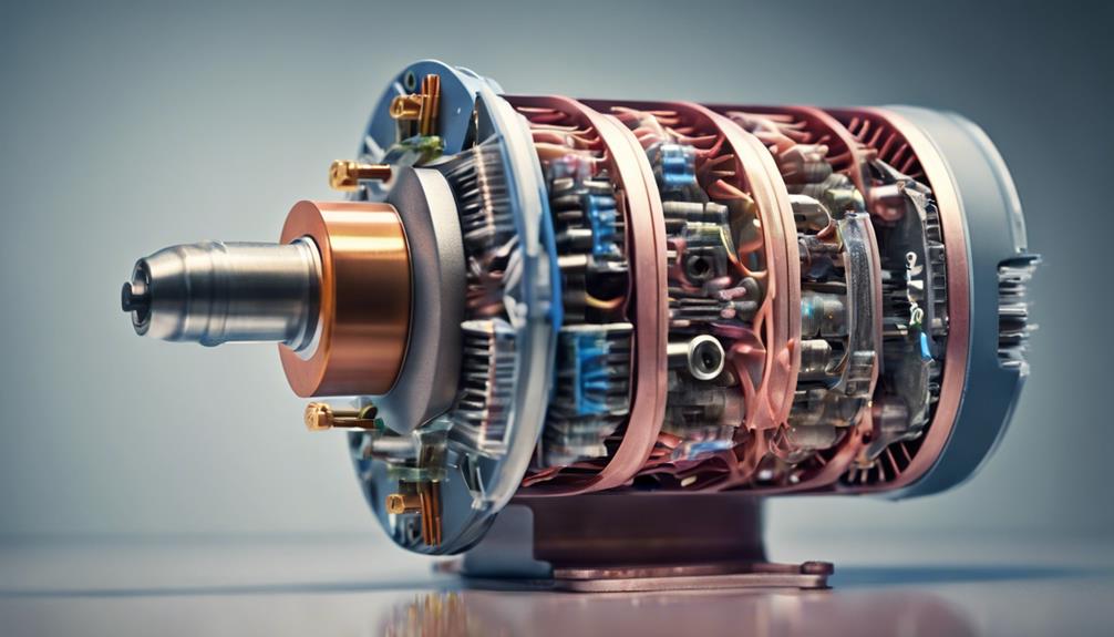
Understanding the construction of a DC motor is essential to grasp its working principle and performance. The motor’s structure includes several key components: the armature, yoke, field windings, commutator, and carbon brushes.
The stator forms the stationary part of the motor, providing structural support and generating the magnetic field. It’s made up of the yoke, poles, and pole shoes. The yoke acts as the outer cover and is designed from a low-reluctance magnetic material, enhancing the magnetic circuit’s efficiency. The poles and pole shoes are designed to create a strong magnetic field and concentrate the magnetic flux toward the armature.
The armature, positioned within the stator, converts electrical energy into mechanical energy. When direct current flows through them, the field windings wrapped around the poles generate the magnetic field, which is essential for motor operation.
To emphasize the main components:
- Yoke – enhances magnetic circuit.
- Poles and Pole Shoes – maximize the flux.
- Field Windings – generate the magnetic field.
- Armature – converts energy.
The commutator and carbon brushes ensure the current direction changes as the motor rotates, maintaining consistent torque. This intricate construction allows the DC motor to function efficiently and reliably.
Working Principle
To understand the working principle of a DC motor, you’ll need to grasp how electromagnetic force is generated when current flows through the armature in a magnetic field.
The commutator and brushes play an essential role by reversing the current direction and maintaining consistent torque.
Additionally, armature reaction effects impact the motor’s performance by influencing the magnetic field distribution.
Electromagnetic Force Generation
In a DC motor, the current flow through the armature windings creates an electromagnetic force that interacts with the magnetic field, causing the armature to rotate. This interaction is the key to converting electrical energy into mechanical energy.
When current flows through the armature windings, the conductor within the magnetic field experiences a force. This force, known as the electromagnetic force, is influenced by several factors:
- Magnetic Field Strength: The stronger the magnetic field, the greater the electromagnetic force.
- Current in the Armature: Higher current increases the electromagnetic force.
- Length of the Conductor: A longer conductor within the magnetic field results in a stronger force.
- Direction of Current and Field: The direction of the electromagnetic force depends on the direction of the current and the orientation of the magnetic field.
Understanding these factors is essential for grasping how a DC motor works.
The direction of the electromagnetic force determines the armature’s rotation, turning electrical energy into mechanical energy. The strength of the electromagnetic force promotes efficient operation and is directly proportional to the magnetic field, current, and conductor length.
Commutator and Brushes
The commutator and brushes in a DC motor play a critical role in facilitating the armature‘s continuous rotation by reversing the current flow in the windings. The commutator, a cylindrical structure composed of copper segments, is integral to this process.
As the armature windings rotate, the commutator switches the direction of the current flow, guaranteeing that the magnetic field remains consistent and effective in driving the motor’s rotation.
Typically made of graphite or carbon, brushes play an essential role by conducting electric current from the external circuit to the commutator. These brushes contact the commutator’s copper segments, enabling a seamless current transfer. This interaction is crucial for maintaining the necessary magnetic field that powers the DC motor.
For efficient operation, the commutator and brushes must be kept in good condition. Regular maintenance ensures uninterrupted current flow and a strong magnetic field, which guarantees smooth and reliable rotation of the armature.
Neglecting this maintenance can lead to reduced performance and potential damage to the motor. By understanding the role of the commutator and brushes, you can appreciate their significance in the overall functionality of a DC motor.
Armature Reaction Effects
Having explored the roles of the commutator and brushes, let’s now examine how armature reaction affects the performance and efficiency of a DC motor.
Armature reaction occurs when the armature current creates its magnetic field, leading to magnetic field distortion within the motor. This distortion causes a shift in the neutral plane, which is the position where no current flows through the brushes.
Armature reaction impacts several key aspects of a DC motor:
- Torque Production: The misalignment of the magnetic fields can reduce the efficiency of torque production.
- Speed Regulation: Variations in magnetic field strength due to armature reaction can lead to fluctuations in motor speed.
- Efficiency: The motor’s overall efficiency decreases due to the increased energy loss caused by magnetic field distortion.
- Compensating Measures: To counteract these effects, compensating windings or interpolates are implemented to stabilize the magnetic field.
Fleming’s Left-Hand Rule

Fleming’s Left Hand Rule lets you determine the direction of force in a DC motor by aligning your thumb, forefinger, and middle finger at right angles. This rule is key to understanding how the interaction between the magnetic field and current produces motion in a DC motor.
When you arrange your fingers in specific orientations, your thumb represents the direction of motion, your forefinger represents the magnetic field, and your middle finger represents the current.
By applying Fleming’s Left Hand Rule, you can easily determine the direction of the force acting on the armature of the DC motor. This is important because the force’s direction directly influences the motor’s motion. This rule provides a visual and practical way to predict how a DC motor will behave when subjected to certain electrical and magnetic conditions.
When you understand the direction of the magnetic field and the current, you can use Fleming’s Left Hand Rule to predict the resulting motion. This helps design and troubleshoot DC motors, ensuring they operate efficiently and as intended.
Back EMF in DC Motor
Often overlooked but essential, back EMF in a DC motor results from the armature’s rotation within the magnetic field, generating a voltage that opposes the applied voltage. This phenomenon stems from Faraday’s law of electromagnetic induction, which states that a change in the magnetic environment of a coil of wire will induce a voltage (or EMF) in the coil.
Lenz’s law further explains that this induced voltage will always counteract the change in current flow that caused it.
Back EMF plays a pivotal role in the operation of a DC motor. Here’s why:
- Regulates Motor Speed: As motor speed increases, so does the back EMF, which limits the current flow, stabilizing the motor’s speed.
- Controls Armature Rotation: By counteracting the applied voltage, back EMF ensures smoother armature rotation and prevents the motor from running too fast.
- Indicates Load Conditions: The magnitude of back EMF is directly proportional to motor speed, helping maintain a steady speed under varying load conditions.
- Enhances Efficiency: Understanding back EMF is essential for effective control and regulation of the motor, ensuring efficient operation.
Significance of Back EMF

Back EMF is essential because it guarantees the DC motor operates efficiently and maintains a stable speed under varying conditions. This self-regulating mechanism hinges on Faraday’s law, where the induced EMF (back EMF) opposes the armature current. As motor speed increases, back EMF rises, reducing the armature current and regulating the motor speed.
The magnitude of back EMF can be calculated using the formula:
[ E = V – I_aR_a ]
Where ( E ) is the back EMF, ( V ) is the supply voltage, ( I_a ) is the armature current, and ( R_a ) is the armature resistance. This formula underlines the significance of back EMF in ensuring motor efficiency.
| Parameter | Symbol | Description |
|---|---|---|
| Back EMF | ( E ) | Induced EMF opposing armature current |
| Armature Current | ( I_a ) | Current flowing through the armature |
| Supply Voltage | ( V ) | Voltage applied to the motor |
| Armature Resistance | ( R_a ) | Resistance of the armature windings |
Applications of DC Motors
DC motors are integral to many modern applications, from electric vehicles and industrial machinery to household appliances and robotics. Due to their ability to provide precise speed control and high torque, you’ll find these motors in numerous settings. They’re essential in scenarios where constant speed control or variable speed control is required for best performance.
Here are some common applications of DC motors:
- Electric Vehicles: DC motors power electric cars, bikes, and scooters, offering high torque and efficient speed control.
- Industrial Machinery: They drive conveyor belts, pumps, and fans, ensuring smooth and reliable operation in manufacturing and production lines.
- Robotics: In robotics, DC motors enable precise motion control, allowing for automation and accurate movements in various robotic systems.
- Household Appliances: These motors are found in power tools, vacuum cleaners, and other appliances and provide efficient and reliable performance.
Additionally, DC motors are invaluable in the medical field, powering devices that require precision and reliability. Their role in automation extends to the aerospace and automotive industries, where their versatility and consistent performance are essential.
DC Motor Vs. AC Motor
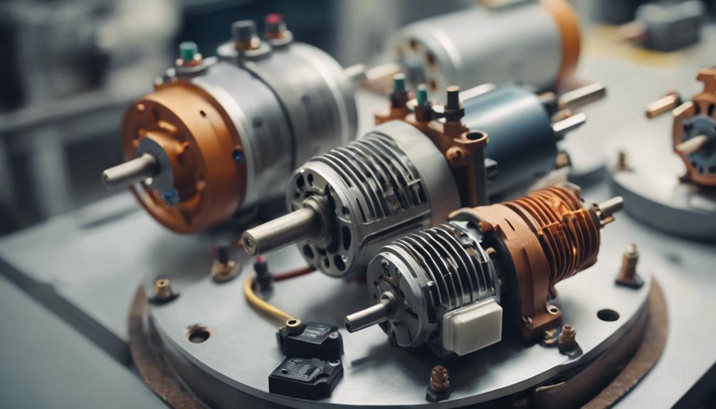
Comparing DC and AC motors helps you understand their unique advantages and applications. DC motors operate on direct current, while AC motors use alternating current. This fundamental difference influences their construction, performance, and suitability for various tasks.
DC motors have a simpler construction compared to AC motors. This simplicity makes DC motors more suitable for specific applications where ease of maintenance and cost-effectiveness are priorities. When it comes to speed control, DC motors excel. Adjusting the voltage allows you to control their speed, offering precise speed regulation easily. This makes DC motors ideal for applications requiring constant speed or variable speed control, such as conveyor belts or electric vehicles.
In contrast, AC motors are commonly found in household appliances and industrial machinery. They’re preferred for their ability to handle high-power applications and robust construction. However, AC motors typically offer less precise speed and torque control than their DC counterparts. This makes them less suitable for applications where fine control is essential.
Ultimately, your choice between a DC motor and an AC motor depends on your specific needs, whether precise speed and torque control with a DC motor or robust performance with an AC motor.
Conclusion
You’ve now clearly understood how a DC motor works. By leveraging the principles of electromagnetism, a DC motor efficiently converts electrical energy into mechanical motion.
The motor maintains continuous rotation with the help of the commutator and brushes. You’ve covered the essentials, whether it’s the construction details, types, or Fleming’s Left Hand Rule.
DC motors are versatile and crucial, making them indispensable in many applications compared to AC motors.
FAQs
What Is the Principle of a DC Motor?
You understand the principle of a DC motor by recognizing that magnetic fields and electrical current interact, causing an armature reaction. The commutator function guarantees torque production, magnetic force, and motor rotation through electromagnetic induction from a direct current power supply.
How Does a DC Motor Work Step by Step?
Start with motor startup to understand a DC motor’s operation step by step. Current flows through the armature winding, interacting with the magnetic field. The commutator segments and brush assembly guarantee continuous rotor movement, enabling efficient energy conversion, speed regulation, and managing load torque through electromagnetic force.
What Is the Working Principle of a Motor?
You’re looking into how a motor works. Magnetic fields and electric current interact within motor components, generating torque. Armature reaction, commutator function, and brush wear impact motor efficiency while induced EMF and electromagnetic force drive motion.
What Is the Principle of DC Motor Control?
You control a DC motor using PWM control and commutation techniques to regulate speed and improve motor efficiency. You manage armature reaction, field weakening, load torque, and brush maintenance to minimize torque ripple and guarantee effective thermal management.
