

Bus Bar Protection Relay | Types, Working & Importance
Kirchhoff’s Current Law in Bus-Bar Protection

Principle And Operation Of Differential Relay
The differential protection principle is based on the concept that the sum of currents entering a protected zone should equal the sum of currents leaving that zone. This principle is derived from Kirchhoff’s current law, which states that the algebraic sum of currents at a node in a circuit is zero.
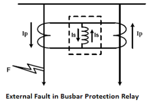
External Faults in Bus-bar Protection Relay
Operation of Bus-Bar Protection Relays during External Faults: Bus-bar protection relays employ several techniques to effectively detect and respond to external faults. The primary principle they rely on is the measurement of current and voltage signals within the protected zone. When an external fault occurs, the currents and voltages within the bus bar are affected, providing indications that can trigger the relay’s protective functions.
Current Measurement
Bus-bar protection relays continuously monitor the currents flowing into and out of the bus-bar. During an external fault, an imbalance in these currents is detected. The relay compares the magnitude and direction of the winds, and if the imbalance exceeds a pre-set threshold, it initiates protective actions.
Voltage Measurement
Voltage measurements are also crucial in detecting external faults. Bus-bar protection relays monitor the voltage levels at the bus-bar terminals. An abrupt change or voltage drop indicates the occurrence of a superficial scar. The relay analyzes the magnitude and duration of the voltage disturbance to confirm the fault and trigger the appropriate protection scheme.
Fault Location and Isolation
Once an external fault is detected, bus-bar protection relays employ fault location algorithms to determine the fault’s location within the power system. This information assists in isolating the faulted section from the rest of the network by opening the relevant circuit breakers. By quickly separating the faulted area, the relay helps minimize the impact of the fault and facilitates the restoration of unaffected portions of the system.
Internal Fault in Bus-bar Protection Relay
Bus-bar protection relays are critical components of electrical power systems that detect and mitigate internal faults within bus bars. This article explores the nature of internal defects in bus bars and how protection relays effectively detect and respond to them.
Understanding Internal Faults: Internal faults in bus bars refer to defects that occur within the protected zone of the bus bar itself. These faults can arise for various reasons, such as insulation breakdown, short circuits between conductors, or equipment malfunctions within the bus-bar system. Internal defects pose a significant risk to the bus bar and the entire power system, and detecting and isolating them promptly is crucial to prevent damage and ensure system stability.

Substation Automation Theory
Components of Substation Automation
IEDs are smart devices that perform various functions within a substation. These devices include protective relays, meters, and programmable logic controllers (PLCs). IEDs are equipped with sensors and communication capabilities to collect and transmit data to the substation automation system.
Communication Networks:
Communication networks are crucial in substation automation, facilitating data exchange between different IEDs and the central control system. These networks can be based on protocols such as Ethernet, IEC 61850, DNP3, or Modbus. They enable real-time monitoring, control, and coordination of devices within the substation.
Central Control System
The central control system serves as the brain of the substation automation, responsible for monitoring, analyzing, and controlling the substation’s operation. It collects data from IEDs, performs data processing and analysis, and initiates appropriate actions based on predefined logic and algorithms. The control system provides operators with a user interface for visualizing and interacting with the substation’s components and data.
Conclusion
Furthermore, bus bar protection relays provide valuable diagnostic information that assists in fault identification and troubleshooting. By monitoring and analyzing the electrical parameters, operators can quickly pinpoint the location and nature of faults, facilitating efficient maintenance and repair activities. This proactive approach not only improves system reliability but also reduces maintenance costs and enhances the overall performance of the bus bar system.
