Theorem

Explanation of Thevenin’s Theorem

Thevenin’s theorem is a fundamental concept in electrical circuit analysis that provides a powerful tool for simplifying complex circuits into simpler equivalents. Named after the French physicist Léon Charles Thévenin, this theorem states that any linear electrical network containing voltage sources, current sources, and resistors can be replaced by an equivalent circuit consisting of a single voltage source and a single resistor. This simplified representation, known as the Thevenin equivalent circuit, allows engineers and scientists to analyze and predict the behavior of complex circuits more easily. By understanding and applying Thevenin’s theorem, we gain valuable insights into circuit analysis and design, enabling us to solve many practical electrical engineering problems.

Statement of Thevenin’s Theorem

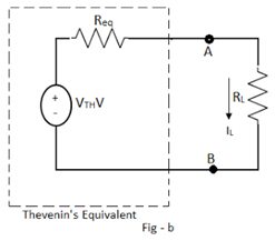
Any permutation of linear bilateral circuit elements and active sources, apart from the connections or complication, connected to a specific load RL possibly will replace by a simple two-terminal network consisting of a single voltage source of Vm volts and a single resistance Req in series with the voltage source, across the two terminals of the resistance load RL. VTH is the open circuit voltage measured at the two terminals of interest, with load resistance RL removed. This voltage is known as Thevenin’s equivalent voltage. The Req is the equivalent resistance of the given network as viewed through the terminals where RL is connected, but with RL removed, all the active sources are replaced by their internal resistances.

Explanation of Thevenin’s Theorem

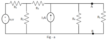
The theory of Thevenin’s equivalent across the terminals of interest can be explained by considering the circuit shown in Fig-a. Terminals A-B are the terminals of interest across which RL is connected. Then Thevenin’s equivalent across the load terminals A-B can be obtained as shown in Fig-b.
explanation-of-thevenin-theorem
thevenin-equivalent

Superposition Theorem

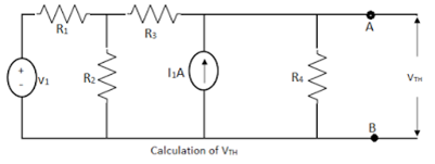
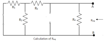
The voltage VTH is obtained across terminals A-B with RL removed. Hence VTH is also called open circuit Thevenin’s voltage. The circuit to calculate VTH is shown in Fig-a for the network considered above. At the same time, Req is the equivalent resistance obtained as viewed through the terminals A-B with RL removed, voltage sources replaced by short circuits, and current sources by an open course. This is shown in Fig – b.
thevenins-voltage
thevenins-equivalent

While obtaining VTH, any of the network simplification techniques can be used. When the circuit is replaced by Thevenin’s equivalent across the load resistance, then the load current can be obtained as

                        IL = VTH/(RL + Req).

By using this theorem, current through any branch of the circuit can be obtained, treating that branch resistance as the load resistance and getting Thevenin’s equivalent across the two terminals of that branch resistance as the load resistance and getting Thevenins equivalent across the two terminals of the branch.

Steps to Apply Thevenin’s Theorem

  1. Remove the branch resistance through which the current is to be calculated.
  2. Calculate the voltage across these open-circuited terminals using any network simplification technique. This is VTH.
  3. Calculate Req as viewed through the two terminals of the branch from which current is calculated by removing that branch resistance and replacing all independent sources with their internal resistances. If the internal resistances are unknown, replace Independent voltage sources with short circuits and independent current sources with open courses.
  4. Draw the Thevenin’s equivalent showing source VTH, with the resistance Req in series, across the terminals of a branch of interest.
  5. Reconnect the branch resistance. Let it be RL. The required current through the branch is given by,
                           I = VTH / (Req + RL)

Limitations of Thevenin’s Theorem

The limitations of Thevenin’s theorem are;
  1. Not applicable to circuits consisting of nonlinear elements.
  2. Not applicable to unilateral networks.
  3. There should not be magnetic coupling between the load and circuit to be replaced by Thevenin’s theorem.
  4. Controlled sources on the load side should not be controlled from another part of the circuit.

Jessica

Jessica, at just 27 years old, is a passionate trailblazer in the world of physics and engineering. Her insatiable curiosity about the mysteries of the universe and a knack for simplifying complex concepts have made her a rising star in the field. As a Quantum Mechanics Enthusiast, Jessica delves into the deepest realms of theoretical physics with a unique and engaging perspective. Her love for unraveling the secrets of the quantum world is infectious, making even the most perplexing ideas accessible to enthusiasts and newcomers alike.

Leave a Reply

Your email address will not be published. Required fields are marked *